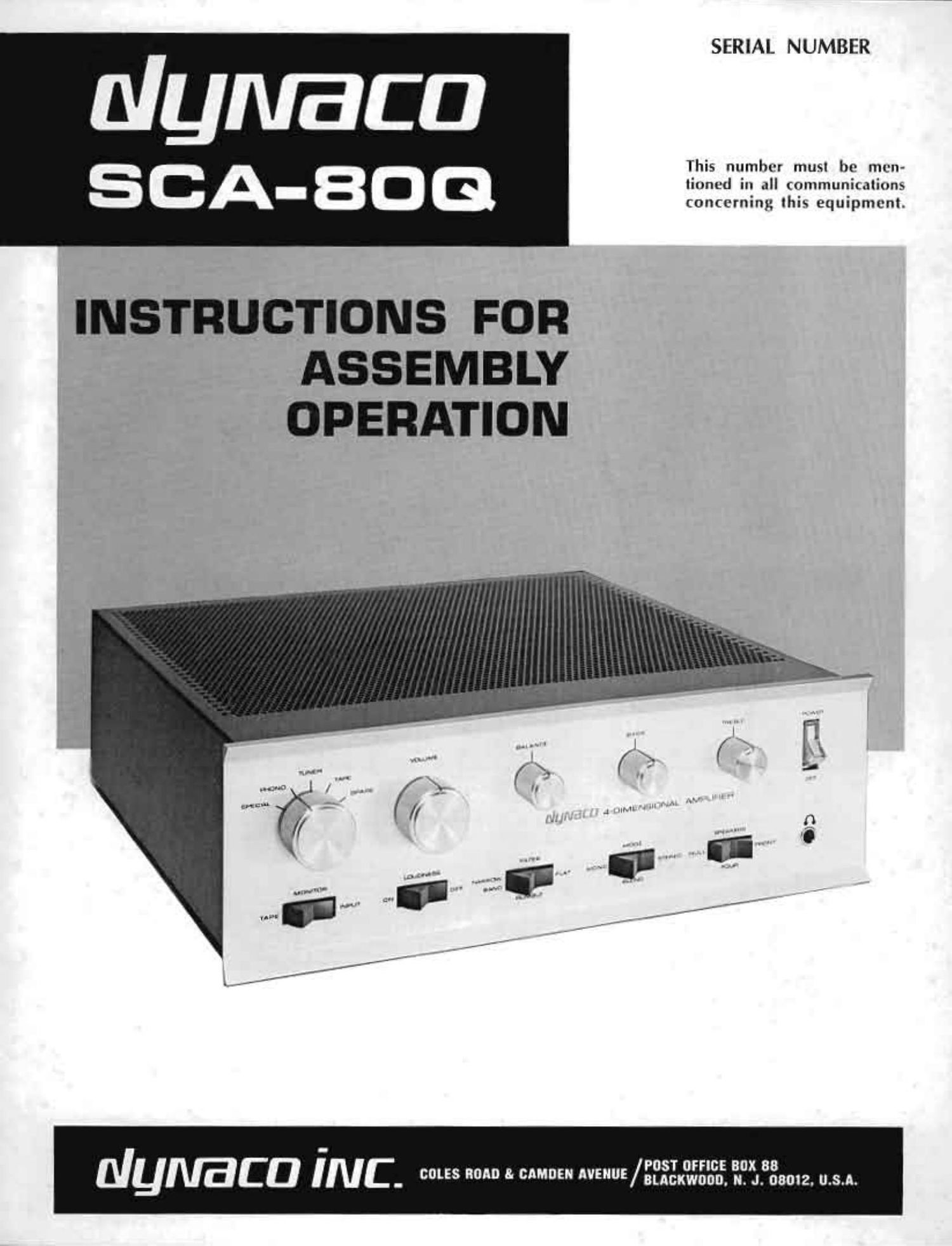
Dynaco SCA 80 Q Owners Manual

This is the 32 pages manual for Dynaco SCA 80 Q Owners Manual.
Read or download the pdf for free. If you want to contribute, please mail your pdfs to info@audioservicemanuals.com.

Page: 1 / 32
left right
Dynaco SCA 80 Q Owners Manual

Extracted text from Dynaco SCA 80 Q Owners Manual (Ocr-read)


Page 1

SERIAL NUMBER

This number musl be men-
Iinncd in all communications
concerning this equipmcnt.

INSTRUCTIONS FOR
ASSEMBLY
OPERATION

POST urns: BOX 88
NUIVBCD I N C - 5 0 3' "05" ""uE/sucxwoon. N. J. 08012. U.S.A.

Page 11

14( )Install the remaining 4-lug screw terminal strip in
the same manner.

15!, )Install one of the AC outlets in the upper location
(marked unswt'tclred on the panel) with two sets of
#4 hardware with the flange inside.

16( )Install the other AC outlet in the lower location
with two sets of #4 hardware.

17( )Install the 4-lug terminal strip TS with one set
of #4 hardware in the hole between the two AC out-
lets. Note the lug placement in the diagram

18( )lnstall the fuse holder below the black AC outlet.
The rubber washer stays outside the panel, and the
flat side of the mounting hole engages a similar flat
on the holder for proper orientation. Secure it with
the lockwasher and nut.

This completes the mechanical assembly of the back
panel. One large hole remains vamnt for the present.
Set this smoothly aside. and place the main chassis bottom
plate in front of you, flanges upwards.

19( )Select the four rubber feet, and four sets of #6
hardware. A foot is mounted in the hole in each
comer of the chassis by turning the bottom plate
over. placing the foot over the hole, and forcing
the screw through the foot until the screw head
is recessed. The foot mounted in the corner where
the power transiormcr will be located should be
mounted loosely, The other three should be fastened
securely. but not so tightly that the foot becomes
distorted.

The next 4 steps describe the installation of the four
capacitor mounting brackets. All mounting screws are
installed from the outside (bottom) of the chassis. One
set of #6 hardware is to be installed in each bracket clamp
before mounting. In each case refer to the diagram for
the correct orientation of the clamp. and also for the direc-
tion of insertion of the clamping screw. This will facilitate
servicing access if required in the future.

Because the brackets are flexible. you will find that the
capacitors will be held most securely it they are tempo-
rarily slipped into each bracket for sizing when the bracket
mounting bolts are tightened. While squeezing the bracket
around the capacitor. tighten all the mounting bolts, start-
ing first with the bolt farthest from the clamp. Then re-
move the capacitor. Do not remove the outer insulation
from any of the three largest capacitors.

20( )Select the 1%" diameter (smaller) bracket and
three sets of #6 hardware. Install it at the left of
the chassis as in the diagram.

21( )Select one of the three larger (2" diameter)
brackets. (on: sets of #6 hardware, and install it as
shown in the diagram at the rear of the chassis.

22( )Install another of the brackets in the right front
comer oi the diassis with four sets of #6 hardware.

23( )Install the renmining bracket on the right side of
fltechaaiswith foursetsofaflihardware.

2 )Install the two U" shaped brackets in an upright
position in the single holes near the front of the
chassis with two sets of #6 hardware.

25( )Remove the foot in the right rear corner of the
chassis and install the power transformer with the
two red loads toward the center of the chassis. using
three additional sets of #6 hardware. Reinstall the
foot and tighten it securely.

26( )Select one of the two long narrow circuit boards,
PC-l'r'. and four sets of #4 hardware. To facilitate
wiring in later steps, you should remove the solder
which fills eyelets 3, 4, 11 and 12 of this board.
Heat each eyelet in turn with the soldering iron.
and then clear the eyelet with a toothpick. Be caro-
ful that no solder splashes onto other parts of the
circuitry on the board. Install this board on the
rear inside of the two "U" shaped brackets with
the row of eyelets on top, and the components on the
side of the board nearest the power transformer.

271 )Inatall the remaining PC-l? board with four sets of
#4 hardware on the front outside of the two
brackets, with the eyelets on top, and the com.
ponent side of the board nearest the power trans-
former.

Wiring the Main Chassis

The next 4 steps describe the installation of components
on the power supply circuit board P019. The placement
of each part is marked on the side of the board on which
most of the components are mounted by lines to the holes
into which its leads will be inserted. Dotted lines indicate
parts which are mounted on the reverse (copper) side
of the board. Except where specifically indicated other-
wise, the parts should be mounted tightly against the
board. just as you see those on the other circuit boards
mounted.

Each part will be identified by a part number, color
code. or written value. First bend the leads to fit the
space between the marked holes, then push the leads
through the hole: and spread them slightly to hold the
part in place for soldering. Solder each lead and every
eyelet wrefully to the copper toil, being sure the solder
flows all around the lead and smoothly onto the copper.
without any bridges to other parts of the circuitry. Cut
oi! all excess leads. The copper side of the board has been
coated with a corrosion inhibitor which is also conducive
to soldering, but there is no substitute for good soldering
technique.

2( )Install the four silicon rectifier
diodes #544322, D4, D5, D6 and

1( )Install the 68 ohm resistor tbluegray~black) R21.
D7. Be certain the markings are
all faced the same way, with the

Solder.
cathode end nearest resistor R21.

The ones supplied my be any .
of the three types shown in the
illustration. Although difierent
in a . they are electri-
cally equivalent. Solder.

CATHODE
Alfie