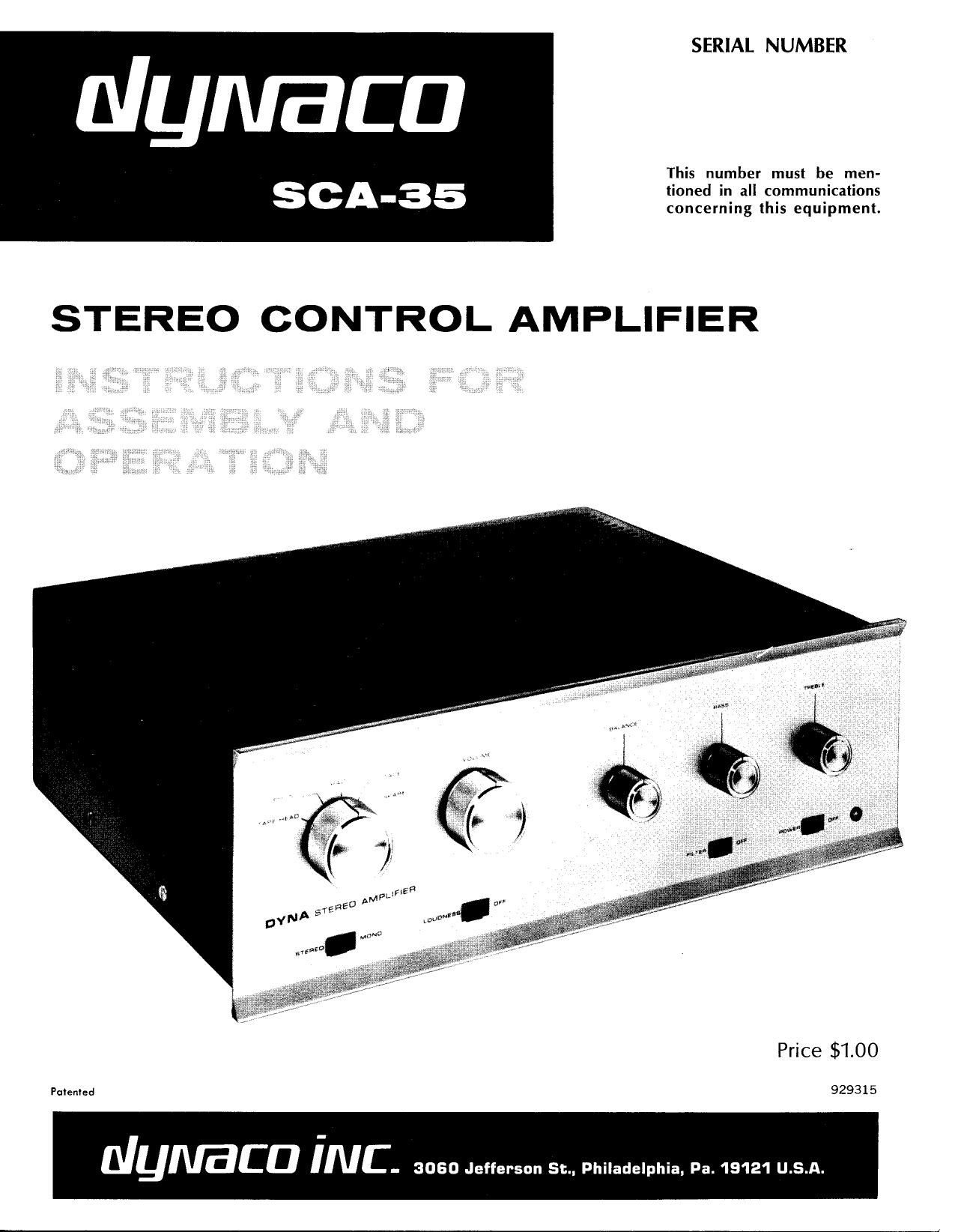
Dynaco SCA 35 Service Manual

This is the 22 pages manual for Dynaco SCA 35 Service Manual.
Read or download the pdf for free. If you want to contribute, please mail your pdfs to info@audioservicemanuals.com.

Page: 1 / 22
left right
Dynaco SCA 35 Service Manual

Extracted text from Dynaco SCA 35 Service Manual (Ocr-read)


Page 1

SERIAL NUMBER

dymaca

This number must be men-

tioned in all communications
- . . .
SCA 35 concerning this eqmpment.

STEREO CONTROL AMPLIFIER

Price $1.00

Pulen'ed 929315

Nymca iNC- 3060 Jefferson St Philadelphia, Pa. 19121 U.S.A.

Page 2

CONTENTS

Operation of Controls . . . .................... . l l . 3

connections to Music System ................... 4

. initial Adjustments and Installation ............. .. 5

d, rconnecting'a Center Loudspeaker ................. 5

, connecting Headphones ....................... 6
- TechnicalCircuit Description . . . l 7 ,
I Assembly Instructions ........ _ ................. _9
L 240 Volt Power Transformer ................... L 16 ,

InVCase of Trouble . . . . .17r
Schematic Diagram ........................... 19 -,
, Service and Warranty .................. I ......... 21 '
._,."Par.ts: List ...... . .............................. 21 -,

SPECIFICATIONS

Inputs: 7 pairs: RIAA magnetic phono low level,
magnetic phono high level (50,000 ohms);
Ceramic phono; NAB 71/2 i.p.s. tape head
(100,000 ohms); radio, tape, spare (250,000 ohms)

Outputs: Constant level tape output, 8 and 16 ohm
loudspeaker outputs, center-channel loudspeaker
output, provision for headphone connection.

Controls: Selector, Volume, Balance, Bass, Treble,
StereoiMono Switch, Loudness Compensation
Switch, Filter Switch, Power Switch.

Tone Control Range: : 12 db at 50 cps and 15 kc.

Sensitivity for 2.5 mv at tape head, 4 mv at low level magnetic
Rated Output: phone, 1 volt at high level inputs.

Power Output: 35 watts continuous, 45 watts IHF
Music Power (both channels).

Frequency Response: : 0.25 db from 20 cps to 20 kc.

Power Response: 20 cps to 20 kc without exceeding 1% distortion
within 1 db of 175 watts (each channel).

IM Distortion: Less than 1% at 17.5 watts (each channel).
Less than 0.2% on any input at average
listening levels.

Hum and Noise: 70 db below 10 millivolt input for rated output
on low level inputs.
80 db down on high level inputs.

Tube Complement: 12AX7/ECC83 (2), 7199 (2),
GBQ5/EL84/7189 (4).

Silicon Diodes: 500 MA, 1000 PIV (2).

Power Consumption: 110 watts, 120 volts 60 cycle AC, or 120/240 volts
50/60 cycle AC with optional PB-O28
power transformer.

Special Features: Attractive Champagnegold anodized aluminum
front panel and die-cast knobs; 2 AC convenience
outlets; provision for headphone output or
center-channel level control; center speaker
output; power transformer sealed in special
encapsulating material for coolest,
quietest operation.

Page 12

MAIN CHASSIS MECHANICAL ASSEMBLY

1( ) Pass the leads of one of the output transformers

2(

3(

4(

0(

6(

7(

8<

12

Z-565 through the two holes provided nearest the
front of the chassis (see the pictorial diagram for
the correct location). The leads of the transformer
are in two groups: the orange, black, and yellow
leads which pass through the rear chassis hole; and
five other leads which pass through the front hole.
Before attaching the transformer to the chassis with
four sets of #8 hardware (the largest size supplied
with the kit), mount a 5-lug terminal strip and the
cable clamp under two of the transformer mounting
screws as indicated on the pictorial diagram. Insert
the lockwasher between the nut and cable clamp,
and between the nut and terminal strip mounting
lug, and under all the other nuts. Do not tighten the
nut under the cable clamp.

') Pass the leads of the power transformer PA-774

through the two holes provided at the rear corner
of the chassis, observing the lead orientation shown
in the pictorial diagram. Mount the transformer
with #8 hardware, and install a 5-lug terminal strip
on one of the mounting screws as shown in the
diagram.

NOTE: Instructions for Pit-028, a 120/240 volt transformer for use
outside the United States, will he found at the end of the regular
assembly instructions.

) Use #8 hardware to mount the other Z-565 output
transformer at the rear of the chassis, in the posi-
tion indicated on the pictorial diagram. The orange,
black and yellow leads should pass through the hole
closest to the rear of the chassis, and the remaining
leads through the other hole.

) Before mounting the two PC-lO circuit boards in-
stall the four sockets supplied for V-5, V-6, V-7 and
V-8 on the top of the boards (the side on which the
components are mounted). Note that the pairs of
sockets on each board do not face in the same direc-
tion, Refer to the pictorial for the correct orienta-
tion. Use #4 hardware; insert the screws from the
bottom of the circuit board and install the locks
washer and nut from the top.

) Mount the two PC-lO circuit boards from the
bottom of the chassis, as shown on the pictorial dia-
gram, using four sets of #4 hardware to mount each
board. Note their orientation, and leave air space
between the boards.

) Mount the P011 preamplifier circuit board in the
position shown on the pictorial diagram, using #4
hardware, from the bottom of the chassis.

) Install the two filter capacitor mounting wafers from
the bottom of the chassis in the cutouts provided at
the rear corner, using two sets of #4 hardware to
secure each wafer,

) The four-section filter capacitor (marked 60/40/20/
100) mounts in the wafer nearest to the center of
the chassis; note the position of the symbols stamped
on the underside of the capacitor, as shown on the
pictorial diagram. The capacitor must be mounted
in this position. Insert the mounting lugs in the slots
provided, from the top of the chassis; check the
diagram to see that the markings are correctly
located. Then, twist each of the mounting lugs
lA-turn with pliers, while holding the capacitor
firmly against the wafer from above.

9(

) The same procedure as in the preceding step is used
to install the two-section filter capacitor (marked
50/50) in the remaining wafer. Note that the
symbols stamped in the underside of the capacitor
are differently positioned than for the other filter
capacitor. Mount the two-section filter capacitor by
inserting and twisting its mounting lugs.

MAIN CHASSIS WIRING

The leads of the transformers may often be somewhat
longer than is necessary to make the connections required
with proper lead positioning. In each case where a trans-
former lead is to be connected, first run the lead to its
connection point, following the path shown in the pictorial
diagram. After cutting the proper length of the lead, strip
1/1 of the insulation from the end of the lead, and tin"
the end by heating it and applying solder to it; this pre-
vents fraying strands and ensures a more secure mechani-
cal bond before soldering.

1(

2L

3f

4(

5<

6(

7<

8(
9(

10(

ll(

) Connect the red lead from the rear output trans-
former to lug #4 (square symbol) of the four-
section filter capacitor. See pictorial for wire
position,

) Connect the red lead from the front output trans-
former to lug #4 (square symbol) of the four-
section filter capacitor. See pictorial for wire
position.

) Twist together the blue-and-white and green-and-
white leads from the output transformer nearest to the
front of the chassis. Connect the blue~and~white lead
to pin #7 of V-7 (S). Connect the green-and-white
lead to pin #9 of V-7 (S).

) Twist together the blue and green leads from the
output transformer nearest to the front of the
chassis. Connect the blue lead to pin #7 of V8
(S). Connect the green lead to pin #9 of V-8.

) Twist together the blue-and-white and green-and-
white leads from the output transformer nearest to
to the rear of the chassis. Connect the blue-and-
white lead to pin #7 of V~5 (S). Connect the green-
and-white lead to pin #9 of V-5 (S).

) Twist together the blue and green leads of the out-
put transformer nearest bo the rear of the chassis.
Connect the blue lead to pin #7 of V6 (S). Con-
nect the green lead to pin #9 of V-6.

) Twist together the two red leads from the power
transformer PA-774. Connect either one of the red
leads to lug #4 of terminal strip TS-l,

) Connect the other red power transformer lead to
lug #5 of terminal strip TS-l.

) Connect the red-andyellow power transformer lead
to mounting lug A of the four-section filter capacitor.

) Twist together the brown and brown-and-white leads

from the power transformer. Pass the leads under
the cable clamp, and connect the brown lead to
lug #1 of terminal strip TSv2. Connect the brown-
and-white lead to lug #2 of TS-2.
NOTE: These transformer leads should be inserted
into the eyelet that holds the terminal to the strip,
thereby providing more space on the lug for the
other wires to be connected.

) Twist together the green and green-and-white leads
from the power transformer. Pass these leads under
the cable clamp, and connect the green lead to lug