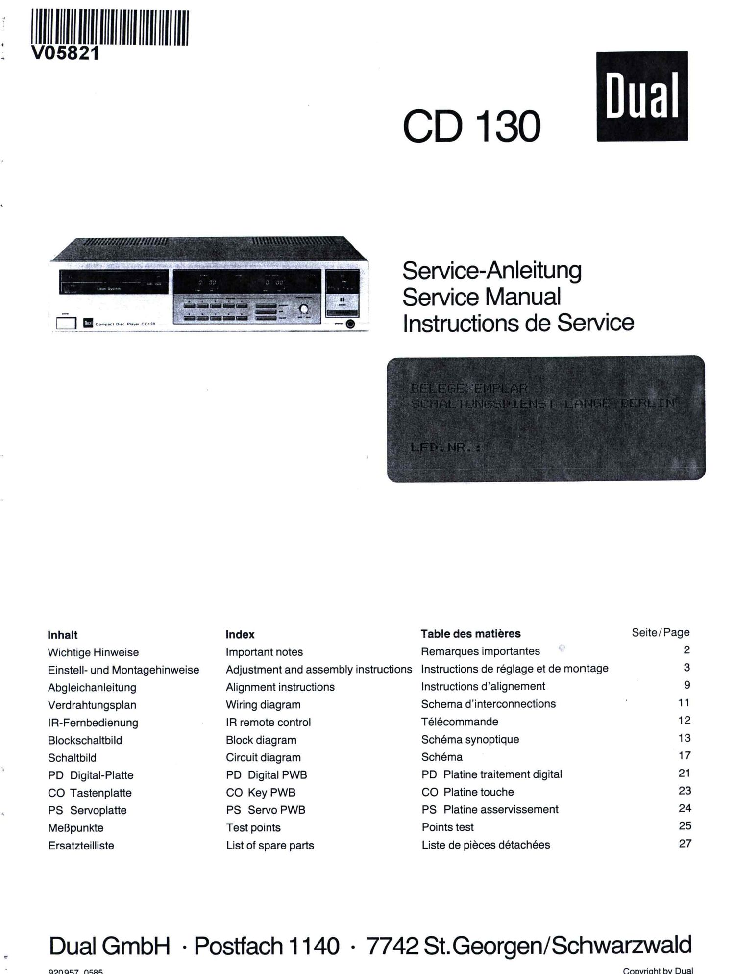
Dual CD 130 Service Manual

This is the 28 pages manual for Dual CD 130 Service Manual.
Read or download the pdf for free. If you want to contribute, please mail your pdfs to info@audioservicemanuals.com.

Page: 1 / 28
left right
Dual CD 130 Service Manual

Extracted text from Dual CD 130 Service Manual (Ocr-read)


Page 1

; willllillmlmumlull

CD 130

I URI Compact an: lev c0130

-.. w~"~~)_ .

Inhalt
Wichtige Hinweise

Einstell- und Montagehinweise

Abgleichanleitung
Verdrahtungsplan
lR-Fernbedienung
Blockschaltbild
Schaltbild

PD Digital-Platte
CO Tastenplatte
PS Servoplatte
MeBpunkte
Ersatzteilliste

.090 987 (IRES

Index

Important notes
Adjustment and assembly instructions
Alignment instructions
Wiring diagram

IR remote control
Block diagram

Circuit diagram

PD Digital PWB

CD Key PWB

PS Servo PWB

Test points

List of spare parts

Service-Anleitung
Service Manual
Instructions de Service

Table des matieres
Remarques importantes
Instructions de réglage et de montage
Instructions dalignement
Schema dinterconnections
Télécommande

Schéma synoptique
Schema

PD Platine traitement digital
CO Platine touche

PS Platine asservissement
Points test

Liste de pieces détachées

Dual

Seite/ Page
2
3
9

11
12
13
17
21
23
24
25
27

Dual GmbH ~Postfach1140 - 7742 St.Georgen/Schwarzwald

Coovrioht bv Dual

Page 2

Wichtlge Hinweise
1. Das Gerat arbeitet mit einem Halbleiter-

Laserstrahl. Direkten Augenkontakt ver-
meiden! Der Laserstrom ist bei geoffneter
Schublade durch Mikroschalter 8002
und zusatzlich bei abgenommenem
Abschirmblech durch Mikroschalter 8001
unterbrochen. Die Laserdiode vor
statischen Entladungen schfltzen!

. Der Abtastschlitten mit Optik und
Lasereinheit und Photodiode sowie die
Schlitten-Fiihrungsschienen sind justiert
und dUrfen nicht zerlegt werden!

Am Pick-up-Schlitten diJrfen die
Schrauben B fiir die Laser-Diode, den
Opto-Sensor C (Fotodiode) und den
Objektivtrager A (Actuator) nicht ver-
stellt oder gelockert werden. Diese Einheit
kann nur komplett beim Hersteller justiert
werden. lm Falle eines Defektes am
Laser, an der Fotodiode oder dem
Actuator, muB die gesamte Pick-up-
Einheit ausgetauscht werden.

Objektivtra'ger

Actuator

Prisma
Right-angular prism

Strahlenteiler
Half prism

Beugungsgitter
Diffraction grating

Polarisationsfilter
Collimator lens

3. Die flexible Leiterbahn sorgfaltig

behandeln, sie kann nicht ausgetauscht
werden! Bei einer Unterbrechung oder
einem anderen Defekt muB auch hier die
gesamte Pick-up-Einheit ausgetauscht
werden. Bei allen Service-Arbeiten muB
darauf geachtet werden, daB das Objektiv
nicht beschmutzt oder beschadigt wird.

. Der Disc-Aufnehmer ist genau eingestellt,
die Disc-Motorachse sollte daher nicht
ausgebaut werden.

Important notes
1. This component operates with a

semiconductor laser beam. Avoid direct
eye contact with the beam! Supply current
to the laser is interrupted by micro-
switch $002 when the drawer is open and
in addition by microswitch 8001 when the
shielding plate is removed. Protect the
laser diode against static discharges!

. The sensor skid with the optics and laser

units as well as the skid guide rails are
aligned and adjusted precisely and may in
no case be disassembled!

On the optic scanner assembly, do not
loosen or readjust screws B on the laser
diode, C on the photodiode and A on the
optic scanner. This assembly can only be
adjusted in the factory. In case of failure of
the laser, the photo diodes or the optic
scanner, the assembly must be replaced.

Remarques Importantes

1.

Cet appareil travaille avec un rayon laser
a semiconducteur. Evitez d'étre en
contact visuel direct avec le rayon laser.
Le courant laser est interrompu en cas de
tiroir ouvert, par le microcontact 8002 et,
en plus, par Ie microcontact 8001 si la
tOIe écran a été retiree.

Protegez la diode laser contre les
décharges statiques.

Le chariot de palpage, avec loptique et
les unites laser, ainsi que les rails de
guidage du chariot de palpage sont
ajustés avec une tres grande precision
et ne devront jamais étre démontés.

Sur l'ensemble de lecture optique ne pas
desserrer ou dérégler les vis B de la diode
laser, C photodiode et A Iecteur optique.
Cet ensemble ne peut étre réglé qu'en
usine. En cas de panne du laser, des
photodiodes ou du lecteur optique
l'ensemble doit etre remplacé.

4-Seg.-Fotodiode
Opto-sensor

dk c

I Fokuslinse

Concave lens

Astigmatische Linse
Cylindrical lens

Sammellinse

Convex lens

. Handle the flexible conductor cables

carefully, as they cannot be replaced!
In case of failure or defect, the optic
scanner assembly must be replaced.
Take care not to soil or damage the
lenses.

. The turntable is adjusted exactly; the

disc motor shaft should therefore not be
removed.

3.

Laserdiode und Monitordiode
Laser diode and Monitor diode

Manipulez avec precaution le circuit
imprimé flexible, il ne peut pas étre
remplacé.

En cas de coupure ou autre défectuosité,
l'ensemble de lecture optique doit etre
remplacé. Prendre soin de ne pas salir ou
endommager l'objectit et les lentilles.

Le plateau at disque est réglé avec
precision, l'axe du moteur disque ne
devrait par consequent pas étre échangé.