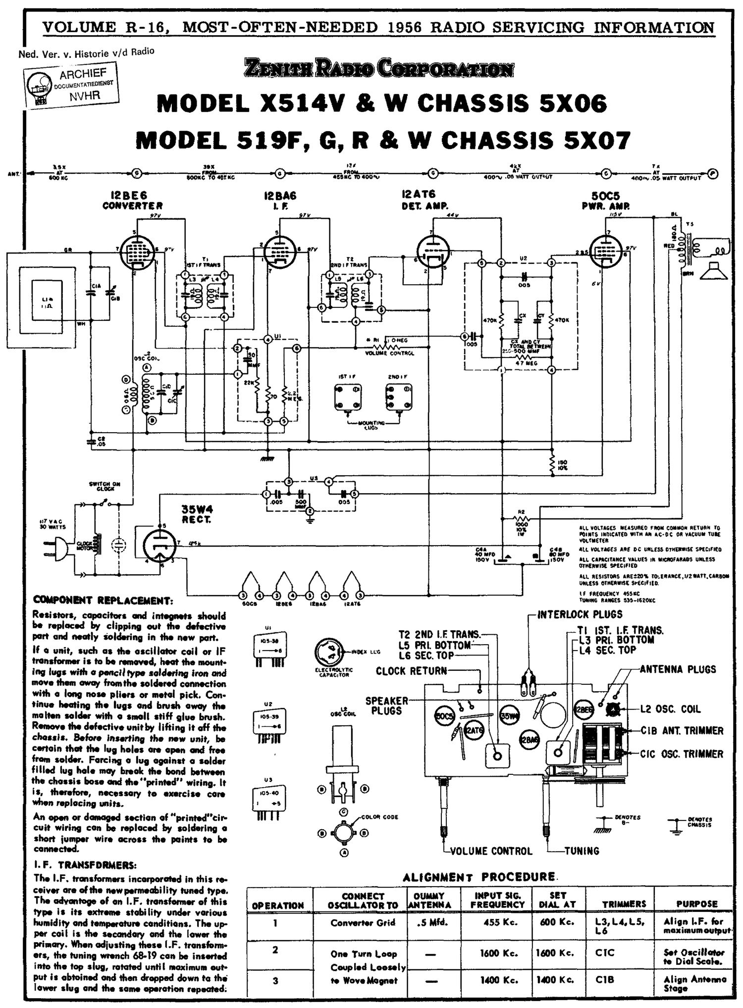
Zenith x 514v

This is the 1 pages manual for zenith x 514v.
Read or download the pdf for free. If you want to contribute, please mail your pdfs to info@audioservicemanuals.com.

Page: 1 / 1
left
zenith x 514v

Extracted text from zenith x 514v (Ocr-read)


Page 1

VOLUME R-16, MOST-OFTEN-NEEDED 1956 RADIO SERVICING INFORMATION

Ned. Ver. v. Historie v/d Radio

MODEL X514V R W CHASSIS 5X06
MODEL 519F, G, R R W CHASSIS 5X07

as I: so: 3 «I: I s
1,- Ws 0 some 0 0:! c 0 new: new» .00,» 3"?- outwt ' W3; WW
l2 8 E 6 I2 BAG I2 ATS 5OC5
CONV£RT£ R I. E DST. 5". PWR. RUB
97V ' I? V 4 y 5 I! IL


I"!
N I F TRANS

Cit
LI
I In

H

I
35:32:; I ILL sonnets nusunco not: comm: new to
i toms Inmates one an Inc-u: on vacuum we:
. :1 (.L. 7 ,. vouuctee
r. " \p e 3: saw IILL VOUMKS A98 oc auras ommst smmeo
: 4 ~45» Ioov . .301: m. CINCITINCE was III umrsuos muss
I museum: soscmco
III. assustons mazes {OLEQIIWJIZNANJQIMI
muss ominous: srecmio
II saeooEIIcv assoc
convenes? nauseous. 9°. 9...: Mg... mm «mm m-wm
assist? «gears and integeets should INTERLOCK PLUGS
repoced c Ipping out the defective
port and neatly 8'0.an in the new part. T2 2ND l.F. Tamer-1 -~_T| IST- EEJIOIR
. L5 PRI BOTTou-w-a L3 m-
'f 0 Ill, '"d 0 I. CSCIIIW C0 0" IF © .350 L00 L5 SEC. top ILA' SEC. TOP
tronsionnet' Is to be removed. heat the mounto I

RNTEN NA PLUGS


"'9 I993 ""3" 0 Pencil type soldering iron om! [iigi'ilig'c CLOCK RETURN
move them away Imthe soldered connection

*"I' ° I009 9° pliers or metal pick. Con-
tinue heating the logs and brush away the 2 u SPEAKER

molten solder with 0 small stiff glue brush «coon; PLUGS
I-oe

L2 050. COIL
CIR ANT. TRINIIIER

Remove the detective unitby lifting it off the
chassis. Before inserting the new unit, be "-3
certain that the lug holes are open and tree
from solder Forcing o lug ogoinst o solder

tilled log hole may hteol: the bond between
the chassis hose and the"ptinted" wiring. It 3

is, therefore necessary to exercise can I
When replacing units. (9

An open ot damaged section of printed" cir- come cone
6) dco

CIC OSC. TRIMMER

WTES
I OHSSIS

cuit wiring con be teploced by soldering a
short iompet wire across the points to be '
COMM- G) VOLUME CONTROL TUNING

I. F. TRANSFORMERS:
The LP. transformers incorporated in this re- ALIGNMENT PROCEDURE

coiver ate otthe new permeability toned type. " MY INIUI' SIG.

type Is Its extreme stability under voriws -~ -- - -
humidity and temperature conditiOns. The Up- I Converter Gtiii 600 K; -L3, L4. L5.- Align I. F. for
PM coil is the secondary and the lower the ' "W'WMW'PW
primary. When odiosting these I.F. ttonstoI-m- .

as, the tuning Wench 68-19 can b. 53.3mm] 2 One Turn Loop -m 1600 Kc. 3393ch
into the tap slug, rotated until maximum out. Coupled Loosely '

put is obtoined and then chopped down to the' 3 to Wave 0900* I400 Kc. 1&0 KC. Align Antenna _
lower slug out! the some opetotion repeated; Stoge