Zenith l 565r

This is the 11 pages manual for zenith l 565r.
Read or download the pdf for free. If you want to contribute, please mail your pdfs to info@audioservicemanuals.com.

Page: 1 / 11
left right
zenith l 565r

Extracted text from zenith l 565r (Ocr-read)


Page 1

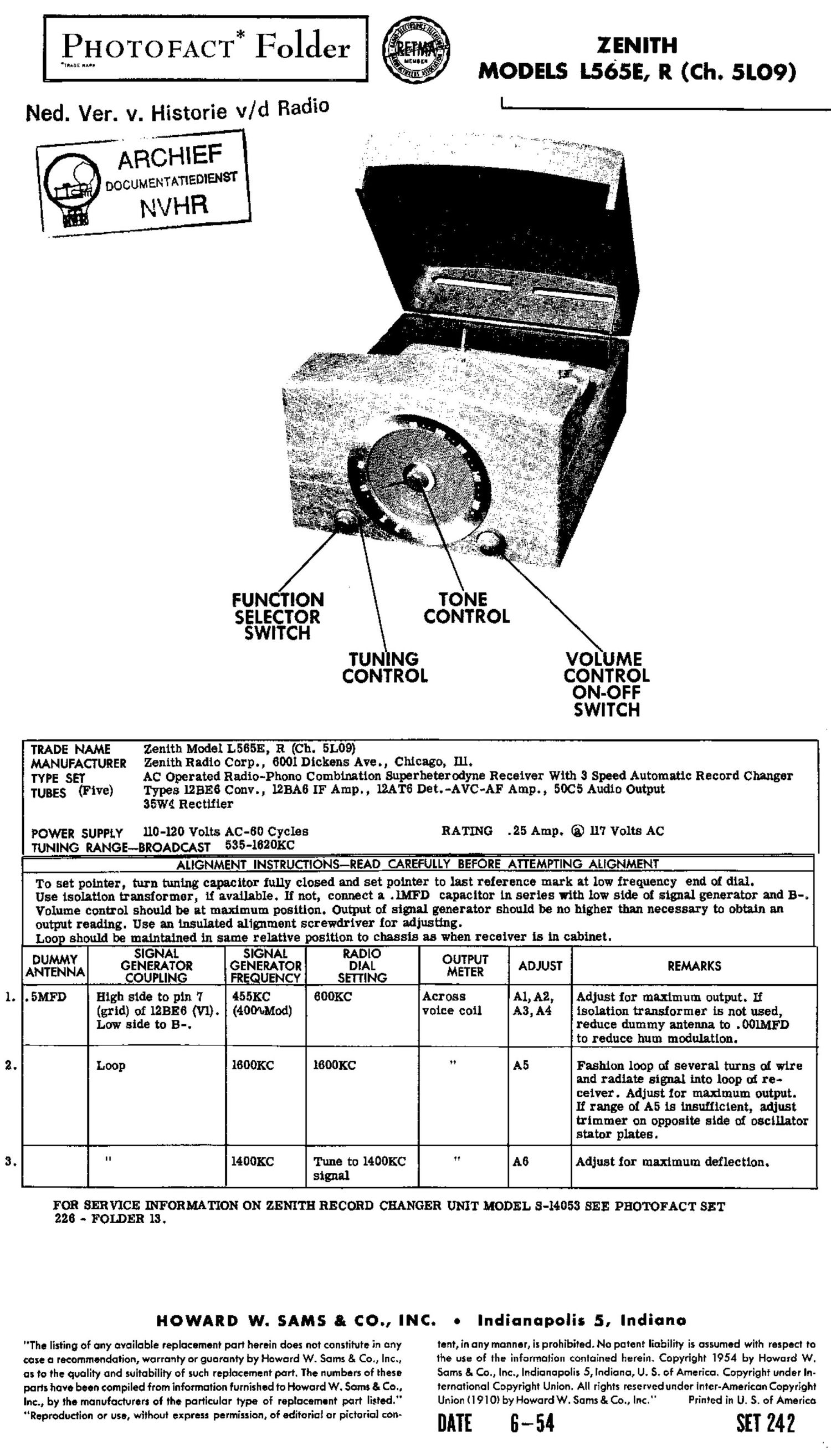
PHOTOFACTa Folder ZENITH


deans... _ __ _ ti? . :43: MODELS L565E R (Ch. Slog)
Ned. Ver. v. Historie v/d Radio L.__ _
ARCHIEF
DOCUMENTATIEDIENST

NVHR

YONE
CONTROL

FUNCTION
SELECTOR
SWITCH

TUN NG VOLUME
CONTROL CONTROL

ON-OFF

SWITCH

TRADE NAME Zenith Model L565E, R (Ch. 51.09}
MANUFACTURER Zenith Radio Corp., 6001 Dickens Ave., Chicago, Ill.
TYPE SET AC Operated Radio-Phone Combination Superheterodyne Receiver With 3 Speed Automatic Record Changer
TUBES (Five) Types lZBEB Conv., 12MB IF Amp. , 12A'l6 Det.-AVC-AF Amp. , 50C5 Audio Output
35": Rectifier

POWER SUPPLY 110-120 Volts lac-so Cycles RATING .25 Amp. ® 117 Volts Ac
TUNING RANGE-wBROADCAST 535-1820KC
ALIGNMENT INSTRUCTIONS-READ CAREFULLY BEFORE ATTEMPTING ALIGNMENT

To set pointer, turn tuning capacitor fully closed and set pointer to last reference mark at low frequency end of dial.

Use isolation transformer, if available. If not, connect a .IMFD capacitor in series with low side of signal generator and B-.
Volume control should be at maximum position. Output of signal generator should be no higher than necessary to obtain an
output reading. Use an insulated alignment screwdriver for adjusting.

Loop should be maintained in same relative position to chassis as when receiver is in cabinet.

SIGNAL SIGNAL RADIO
Agdt'i'mJA GENERATOR GENERATOR DIAL (figs? ADJUST REMARKS
COUPLING FREQUENCY SEITING
. EMFD High side to pin 7 455KC GOOKC Across A1,A2, Adjust for maximum output. If

(grid) of 12BEG (Vi). (4OMMod) voice coil A3,A4 isolation transformer is not used,

Low side to 3-. reduce dummy antenna to .OOLMFD
to reduce hum modulation.

Loop lBOOKC 1600KC A5 Fashion loop of several turns of wire
and radiate signal into loop at re-
ceiver. Adjust ior maximum output.
If range of A5 is insuiiicient, adjust
trimmer on opposite side of oscillator
stator plates.

+ l
" 1400KC Tune to 1400KC " A6 Adjust for maximum deflectiOn.
signal

FOR SERVICE INFORMATION ON ZENITH RECORD CHANGER UNIT MODEL 344053 SEE PHOTOFACT SET
228 - FOLDER 13.

HOWARD W. SAMS 8: CO... INC. 0 Indianapolis 5, Indiana

"The listing of any available replacement part herein does not constitute in any tent, in any manner, is prohibited. No potent liability is assumed with respect to
case a recommendation, warranty or guaranty by Howard W. Sams 8. Co., Inc., the use of the informati0n cantained herein. Copyright 1954 by Howard W.
as to the quality and suitability of such replacement part. The numbers of these Sums 8. (20., Inc., Indianapolis 5, Indiana, U. S. of America. Copyright under In-
parts have been compiled from information furnished to Howard W. Sam: 8- Co., ternational Copyright Union. All rights reserved under Inter-American Copyright
Inc., by the manufacturers of the particular type of replacement part list . Union ( l 9| 0} by Howard W. Sums &Co., Inc." Printed in U. S. of America

Reproduction or use, without express permission, of editorial or pictorial con- DATE 6 __ 54 SET 242

Page 2

PARTS LIST AND DESCRIPTIONS
MODEL L56
TUBES (SYLVANIA, GENERAL ELECTRIC, WESTINGHOUSE)
REPLACEMENT DATA " ' _
ITEM RETMA
Na. USE ZENITH STANDARD BASE NOTES
PART No. REPLACEMENT TYPE
V1 Converter lZBEfi 12BE6 7CH
V2 IF Amplifier 12BA6 128118 713K
03 Det.-Avc-AF Amp. 12AT6 12AT8 713T
04 Audio Output 5005 5005 70v
vs Rectifier 351174 35104 5BQ
CAPACITORS
Capacity values given in the rating column are in mfd. [or Electrolytic
and Paper Capacitors, and in mmfd. for Mica and Ceramic Capacitors.
RATING REPLACEMENT DATA
'1? up vou- ZENITH AEROVOX ICENTRALAB gfigfifg ERIE mucky SPMGUE NOTE;
- PART No. PART No. PART No. PART No. PART No. PART No. PART No.
01A .80 150 22-2272 AFH3-13 0012 [FP216 R1040
B 140 150 T045
0 20 150
02 .05 200 22-829 p288-05 DF-503 PJ285 p'r415 ZTM-SS
03 no 22-5 $1110 06-111 szx-m
04 10000 22-3 BPD-Ol DD-103 K082 811-01 130-511 SHK-Sl
05 .05 200 22-820 19283-05 DF-503 P1285 PT415 ZTM-85
08 .01 200 22-828 P288-01 118-103 P1281 092-333-103 pun 2TM-81
07 4000 22-4 13129-004 DD-402 K078 801-004 130-524 51114-04
08 10000 22-3 EDD-01 DD-103 K082 811-01 110-511 511K-Sl
08 4000 22-4 13110-004 DD-402 K078 801-004 D0-524 511K-D4
010 .05 200 22-178 0288-05 DF-503 91285 PT415 2TM-35
011 10000 22-3 EDD-01 DD-103 K082 811-01 00-511 SHK-Sl
012 470 22-8 EDD-00047 136-471 K080 Gp2K-471 00-5347 50A-T47
013 .01 400 22-1182 P488-01 08-103 CUB431 GP2-333-103 p'r411 4TM-Sl
014 .01 BPD-Ol DD 403 K082 811-01 Dc-511 SHK-Sl
015 .05 200 22-829 P288-05 PJ285 PT415 2TM-85
ITEM RATING REPLACEMENT DATA
No RESIST ZENITH IRC CLAROSTAT CENTRALAB MALLORY INSTALLATION NOTES
' ANCE WATTS PART No. PART No. PART No. PARI No. PART No.
81A 5001; 5 83-2270 011-133 A47-500K-S AB-SB 0-50 Volume
B 811311 Not Req. Not Req. KSS-S AK -4 Not Req. Attach to RIA
0 Switch Not Req. 78-1 SWE-lz KB-l 08-28 Attach to 81A
1121. 500110 3:, 83-2289 011-133 A47-500K-S AB-59 0-50 Tone
B Shaft Not Req. Not Req. K8803 1111-4 Not Req. Attach to 112.4
REPLACEMENT DATA REPLACEMENT DATA
ITEM RATING ITEM RATING
OHMS WATT» PART N°~ _ PART No. OHMS WATT PART No. PART No.
R3 10110 3 83-1828 BTS-IOK 812 470140 5 83-1838 HTS-470K
R4 15 Meg 5 83-1981 BTS-lSMeg 103 22000 5 83-1800 BTS-2200
R5 3. 3Meg % 83-1933 BTs-3.3Meg 81410000 1 83-1574 ETA-1000
Rs 1200 '37 83-1747 BTS-IZO 1115 10140 5 83-1828 BTS-lOK
R7 4. 7Meg 1; 83-1940 BT8-470Meg R16 15000 8 83-1793 HTS-1500
R8 2. 2Meg 5 83-1928 BTS-2.2Meg 11171500 1 83-1877 ETA-150
R9 4. 7Meg é- 83-1940 BTS-4.7Meg R18 220 1 83-1450
R10 470K0 5 83-1888 HTS-470K R19 220140 5 83-1884 HTS-220K
101 8200 % 63-1'T82 BTS-BZO
TRANSFORMER (AUDIO OUTPUT)
A REPLACEMENT DATA
ELEM IMPEDANCE ZENITH Sfoncor Meril Triad Holldomon Thordorson NOTES
T1 2.3110 3. 20 206-697 11-3330 (1') 11-3031 (D 21105 (D TS-24S5Oa (D Drill one new mounting
hole.