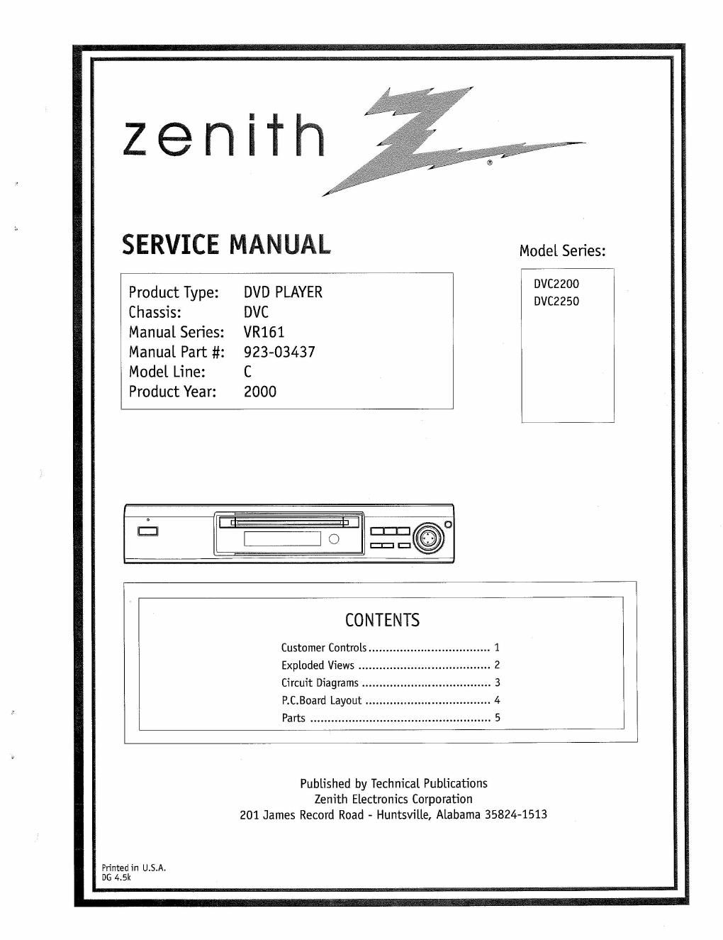
Zenith dvc 2200 2250 service en

This is the 54 pages manual for zenith dvc 2200 2250 service en.
Read or download the pdf for free. If you want to contribute, please mail your pdfs to info@audioservicemanuals.com.

Page: 1 / 54
left right
zenith dvc 2200 2250 service en

Extracted text from zenith dvc 2200 2250 service en (Ocr-read)


Page 1

zenith

SERVICE MANUAL Model Series:

Product Type: DVD PLAYER 38:23
Chassis: DVC

Manual Series: VR161
Manual Part #2 923-03437
Model Line: C

Product Year: 2000

CONTENTS

Customer Controls ................................... 1
Exploded Views ......

Circuit Diagrams ..................................... 3
P.C.Board Layout .................................... 4
Parts .................................................... 5

Published by Technical Publications
Zenith Electronics Corporation
201 James Record Road - Huntsville, Alabama 35824-1513

Printed in U.S.A.
DG 4.5k

Page 2

PRODUCT SAFETY SERVICING GUIDELINES FOR AUDIO-VIDEO PRODU

IMPORTANT SAFETY NOTICE
This manual was prepared for use only by properly trained audio-visual service
technicians.

When servicing this product, under no circumstances should the original design
be modified or altered without permission from Zenith Electronics Corporation.
All components should be replaced only with types identical to those in the
original circuit and their physical location, wiring and lead dress must conform
to original layout upon completion of repairs.

Special components are also used to prevent x-radiation, shock and fire hazard.
These components are indicated by the letter x" included in their component
designators and are required to maintain safe performance. No deviations are
allowed without prior approval by Zenith Electronics Corpomtion.

Circuit diagrams may occasionally differ from the actual circuit used. This way,
implementation of the latest safety and performance improvement changes into
the set is not delayed until the new service literature is printed.

CAUTION: Do not attempt to modify this product in any way. Never perform
customized installations without manufacturers approval. Unauthorized
modifications will not only void the warranty, but may lead to property damage
or user injury.

Service work should be performed only after you are thoroughly familiar with
these safety checks and servicing guidelines.

GRAPHIC SYMBOLS

The exclamation point within an equilateral triangle is intended
to alert the sen/ice personnel to important safety information in
the service literature

The lightning flash with arrowhead symbol within an equilateral
triangle is intended to alert the service personnelto the presence
of noninsulated dangerous voltage that may be of sufficient
magnitude to constitute a risk of electric shock.

The pictorial representation of a fuse and its rating within an
equilateral triangle is intended to convey to the service personnel
the following fuse replacement caution notice:

CAUTION: FOR CONTINUED PROTECTION AGAINST RISK OF FIRE.
REPLACE ALL FUSES WITH THE SAME TYPE AND RATING AS MARKED
NEAR EACH FUSE.

SERVICE INFORMATION

While servicing, use an isolation transformer for protection from AC line shock.
After the original service problem has been corrected, make a check of the
following:

FIRE AND SHOCK HAZARD

1. Be sure that all components are positioned to avoid a possibility of adjacent
component sham. This is especially important on items transported to and
from the repair shop.

2. Verify that all protective devices such as insulators, barriers, covers, shields,
strain reliefs, power supply cords, and other hardware have been reinstalled
per the originaldesign. Be sure that the safety purpose of the polarized line
plug has not been defeated.

3. Soldering must be inspected to discover possible cold solder joints, solder
splashes, or sharp solder points. Be certain to remove all loose foreign par-
ticles.

4. Check for physical evidence of damage or deterioration to parts and compo-
nents. for frayed leads or damaged insulation (including the AC cord), and
replace if necessary.

5. No lead or component should touch a receiving tube or a resistor rated at 1
watt or more. Lead tension around protmding metal surfaces must be avoided.

6. After re-assembly of the set, always perform an AC leakage test on all ex-
posed metallic parts of the cabinet (the channel selector knobs, antenna
terminals. handle and screws) to be sure that set is safe to operate without
danger of electrical shock. 00 NOT USE A LINE ISOLATION TRANSFORMER
DURING THIS TEST. Use an AC voltmeter having 5000 ohms per volt or more
sensitivity in the following manner: Connect a 150!) ohm, 10 watt resistor,
paralleled by a .15 mid 150V AC type capacitor between a known
good earth ground water pipe, conduit, etc.) and the exposed metallic parts,
one at a time. Measure the AC voltage across the combination of 1500 ohm
resistor and .15 mfd capacitor. Reverse the AC plug by using a non-polarized
adaptor and repeat AC voltage measurements for each exposed metallic part.
Voltage measured must not exceed 0.75 volts RMS. This corresponds to 0.5
milliamp AC. Any value exceeding this limit constitutes a potential shock
hazard and must be corrected immediately.

A.C. Voltmeler

Place this probe
Good Earth Ground on each exposed

such aslhe Water ; 1600 oHM metfilparl.

Pipe, Conduit, etc.

10 WATT

X-RADIATION

1. Be sure procedures and instructions to all service personnel cover the subject
of xAradiation. The only potential source of x-rays in current TV receivers is
the picture tube. However, this tube does not emit x-rays when the HV is at
the Emory-specified level. The proper value is given in the applicable
schematic. Operation at higher voltages may cause a failure of the picture
tube or high-voltage supply and, under certain circumstances may produce
radiation in excess of desirable levels.

2. Only fictory-specified CRT anode connectors must be used.

3. It is essential that the service personnel have available an accurate and
reliable high-voltage meter.

4. When the highevoltage circuitry is operating properly, there is no possibility
of an x-radiation problem. Everytime a color chassis is serviced, die brightness
should be run up and down while monitoring the high voltage with a meter,
to be certain that the high voltage does not exceed the specified value and
that it is regulating correctly.

5. When troubleshooting and making test measurements in a product with a
problem of excessively high voltage, avoid being unnecessarily close to the
picture tube and the high voltage power supply. Do not operate the product
longer than necessary to locate the cause of excessive voltage.

6. Refer to HV. 5+, and shutdown adjustment procedures described in the
appropriate schematics and diagrams (where used).

IMPLOSION
1. All direct view picture tubes are equipped with an integral implosion
protection system; take care to avoid damage during installation.

2. Use only the recommended factory replacement tubes.

TIPS ON PROPER INSTALLATION
1. Never install any receiverin a closed-in recess, cubbyhole, or closely fitting
shelf space over, or close to, a heat duct, or in the path of heated air flow.

2. Avoid conditions of high humidity such as: outdoor patio installations where
dew is a factor, near steam radiators where steam leakage is a factor, etc.

3. Avoid placement where draperies may obstruct venting. The customershould
also avoid the use ofdecorative scarves or other coverings that might obstruct
ventilation.

4. Wall- and shelf»mounted installations using a commercial mounting kit must
follow the factoryapproved mounting instructions. A product mounted to a
shelf or platform must retain its original feet (or the equivalent thickness in
spacers) to provide adequate air flow across the bottom. Bolts or screws
used for fasteners must not touch any parts or wiring. Perform leakage team
on customized installations.

5. Caution customers against mounting a product on a sloping shelf or in a
tilted position, unless the receiver is properly secured.

6. A product on a roll-about cart should be stable in its mounting to the cart.
Caution the customer on the hazards of trying to roll a cart with small
casters across thresholds or deep pile carpets.

7. Caution customers against using a cart or stand that has not been listed by
Undenuriters Laboratories, Inc. for use with its specific model oftelevision
receiver or generically approved for use with TVs of the same or larger screen
size.

8. Caution customers against using extension cords. Explain that a forest of
extensions, sprouting from a single outlet, can lead to disastrous
consequences to home and family.

CM151

(IN-001C SAFETY