Yamaha sy 2 service manual

This is the 49 pages manual for yamaha sy 2 service manual.
Read or download the pdf for free. If you want to contribute, please mail your pdfs to info@audioservicemanuals.com.

Page: 1 / 49
left right
yamaha sy 2 service manual

Extracted text from yamaha sy 2 service manual (Ocr-read)


Page 1

(

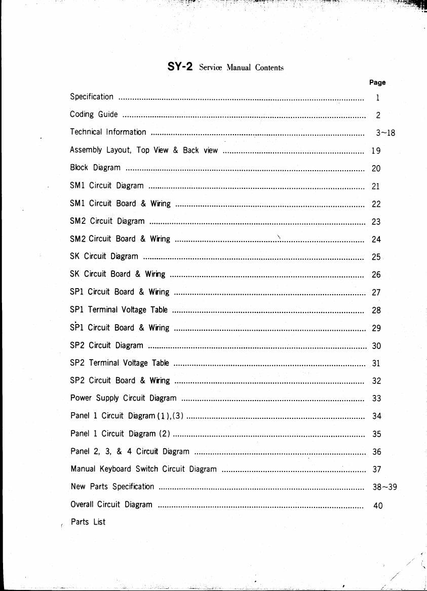
SY-2 Service Manual Contents

Page
Specification ................................................................................................. V ........... 1
Coding Guide ........................................................................................................... 2
Technical Information .............................................. _ ................................................ 3 ~18
Assembly Layout, Top View & Back view ............................................................ 19
Block Diagram ......................................................................................................... 20
SMI Circuit Diagram ............................................................................................... 21
SM Circuit Board & Wiring ................................................................................... 22
5M2 Circuit Diagram ............................................................................................... 23
8M2 Circuit Board & Wiring ............................................. F. .................................... 24
SK Circuit Diagram ................................................................................................. 25
SK Circuit Board & Wiring ..................................................................................... 26
SP1 Circuit Board & Wiring 27
SP1 Terminal Voltage Table .................................................................................... 28
SP1 Circuit Board & Wiring .................................................................................... 29
SP2 Circuit Diagram ................................................................................................ 30
SP2 Terminal Voltage Table .................................................................................... 31
SP2 Circuit Board & W'ring ................................................................................... 32
Power Supply Circuit Diagram ................................................................................ 33
Panel 1 Circuit Diagramll).(3) .............................................................................. 34
Panel 1 Circuit Diagram (2) .................................................................................... 35
Panel 2, 3, & 4 Circuit Diagram .................................................. . ......................... 3 6
Manual Keyboard Switch Circuit Diagram .......... 37
New Parts Specification .......................................................................................... 38~39
Overall Circuit Diagram .......................................................................................... 40

Parts List

Page 2

KEYBOARD 37 keys Cz~Cs
PRESET TONE LEVERS

Side 1
Flute
Trombone
Trumpet
Saxophone
Oboe
Bow Violin
Pano
Harpsichord
Contrabass
Tuba
Bass Guitar
Funny
Trumute
Doubb

Side 11
Clarinet
Bassoon
French Horn
Bass Clarinet

English Horn
Pizzicato String
Guitar

Hawaiian Guitar
Pizzicato Bass
Sousaphone
Wah Guitar
Drake
Growl
Reed
Side I/Side 11 Selector
FILTER CONTROLS
Preset/Control Selector
Low Pass Frequency
Low Pass Resonance
High Pass Frequency
High Pass Resonance
ENVELOPE CONTROLS
Preset/Control Selector
Attack Time
Decay Time
Sustain Level
Release Time
VIBRATO CONTROLS
Preset/Control Selector
Speed
Depth

SY-2

Specifications

TRANSPOSITION LEVERS
One Octave Down
Normal
One Octave Up
Two Octaves Up
TOUCH CONTROLS
Vibrato Depth(On/Off)
Wah-Wah(0n/Off)
Volume(On/Oft)
Sensitivity
FOOT CONTROLS
Wah-Wah (On/Off)
Volume Sensitivity
TONE BEND CONTROLS
Preset/Control Selector
Attack Time
intensity
Decay Time
PITCH BEND CONTROL
On/Off Selector
PORTAMENTO CONTROLS
0n/0ff Selector
Time
PULSE WIDTH CONTROLS
Preset/Control Selector
Width
OTHER CONTROLS
Tune
Master Volume
OTHER FITTINGS
Outputs
Phone Jack
Pin Jack
Level Switch(High/Low)
Foot Controller Jack
Power Switch
Pilot Lamp
Music Rest
CIRCUITRY
Solid State
Power Consumption: 20 Watts
PovVer Source: AC. 50/60Hz
DIMENSIONS

Width: 90cm (35X")
Depth: 32cm (12%")
Height: 17cm (6%") without legs
20cm (8") with case
WEIGHT 21kg (46 lbs.)
FINISH Black Leatherette Siding
ATTACHMENT Foot Pedal