Yamaha rx v567 schematic

This is the 49 pages manual for yamaha rx v567 schematic.
Read or download the pdf for free. If you want to contribute, please mail your pdfs to info@audioservicemanuals.com.

Page: 1 / 49
left right
yamaha rx v567 schematic

Extracted text from yamaha rx v567 schematic (Ocr-read)


Page 1

AV RECEIVER

RX-V567WTR3

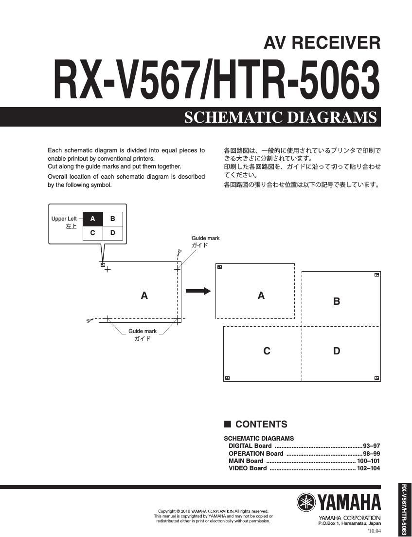
Each schematic diagram is divided into equal pieces to glflfilli. -fi§WIZl§Ffi3hTL/Z>7U DQTEDfiIJ'C"

enable printout by conventional printers. fiéfififillfigfléhfbial

Cut along the guide marks and put them together. EUEIJ LTC§EI$§IEK 7jf IKICSSD'CtDJ-(EEU ébfl
Overall location of each schematic diagram is described T< Tififbo

by the following symbol. §1§I%-U)§EU fibfllfiififll-XFUDEE??? LTLijl

Upper Left A

B
EJ:
o .
Guide mark
fli 7j4 F

Guide mark
754 F

E E9

I CONTENTS

SCHEMATIC DIAGRAMS
DIGITAL Board 93-97
OPERATION Board ...98-99
MAIN Board . ..100-101
VIDEO Board ..102-104

Copyright © 2010 YAMAHA CORPORATION All rights reserved. YAM AH A

ms manual is copyrighted by YAMAHA and mav not be copied or YAMAHA CORPORATION

redistributed eitherin rim or eleclronicall Without emHSSIon
9 V p P.O.Box 1, Hamamalsu. Japan

10.04

I
5
<
m
as
1
I
-I
3.
01
o
as
u