Yamaha rx 930

This is the 47 pages manual for yamaha rx 930.
Read or download the pdf for free. If you want to contribute, please mail your pdfs to info@audioservicemanuals.com.

Page: 1 / 47
left right
yamaha rx 930

Extracted text from yamaha rx 930 (Ocr-read)


Page 1

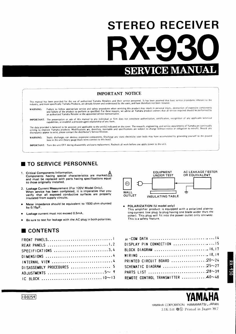
STEREO RECEIVER

RX-93O

SERVICE MANUAL

This manuzl has been prowdcd for the use of muthoriled Yamaha Retailers and their service personnely I! has been assumed that basil zcrvicE procedures when"! lo the 1
WARNING: FIIIU'C m foilow appropriate

and failure ol the product to perform as specifisd. For these reasons. we advisc ali Yamaha product owners did! all service required should be performed by

in an litomcd Yamaha Retaiier or the appointed service reorescnulivet

IMPORTANT. The presenulion or SEIe of this manual to any individual or firm does not constitute authorization, certification, recognition of any applicable lecnnlul
capabilliies, or establish n princiuie-agenr relationship or any Iorm.

in: data proyiam is believed to be accurate and Applicable [0 me with) lndlcned on the covart The research. engineering, and sew e departments of Yamaha are ronmuruy
iIC: or obligation m rermn: Shoud any

striving to improve Yamaha products. Modifications are, therefor vrzatrie and soacitnanons are subject to Change without
discrepancy .ppm to exist, piem mnucl me distributor's Service Division

l
i industry and more specifically Yamaha Products, are already known and understood by The users, and hive Merefore not been 'nsuled,
I
I
r
l
l

WARNING: Static discharges can desuoy expensive Components DzsLliarge anv mric electricity your body may have aLcumulatcd by grounding yourself m in: ground
buss In the unit (heavy gauge black wires connect in (MK buss).

IMPORTANT Turn the unit OFT during disassemhlv and parts 1epIaCemeni,Rcchtck all werk before you apply power to the WIL i

I TO SERVICE PERSONNEL

1r Critical Components Information , A EQUIPMENT AC LEAKAGE TESTER
Components having special characteristics are marked UNDER TEST OR EQUIVALENT
and must be replaced with parts having specifinations equal

to those originally installed. ® I:

2. Leakage Current Measurement (For 120V Model Only).
When service has been carripleted, it is imperatitle that you WALL I:
verify that all exposed conductive surfaces are properlv OUTLET :
insulated from supply circuits. INSULATING TABLE
0 Meter impedance should be equivalent to 1500 ohm shunted
by 0-15IJF- O POLARIZATION (U model only)
This amplifier product is equipped With a polarized alierna-
0 Leakage current must not exceed 0V5mA, tingcurrent line plug (a plug havxng one blade wider than the
other). This plug WIII fit into the power Outlet only on: way.
I Be sure to test for leakage with the AC plug in both polarities. This is a safety feature.

I CONTENTS

FRONT PANELSI u-COM DATA -IL
REAR PANELS.............................|.2 DISPLAY PIN CONNECTION. ....... ........-...IS
SPECIFICATIONS 3.4 BLOCK DIAGRAM -l6l7
DIMENSIONS..................14 WIRING................,..............r.l8.|9

INTERNAL VIEWL PRINTED CIRCUIT BOARD...... ...... .....20~24
DlSASSEMBLY PROCEDURES . 5 SCHEMATIC DIAGRAM .H_25~27
ADJUSTMENTS...........................5~9 PARTS LIST.... ..... .........r28~3

IC BLOCK |0~I3 REMOTE CONTROL TRANSMITTER ___..1.0~I,g

YAMAHA

YAMAHA CORPORATION HAMAMATSJ . JAPAN
3 (in «26) Printed in Jnrzm '89:]

(Jib-XII