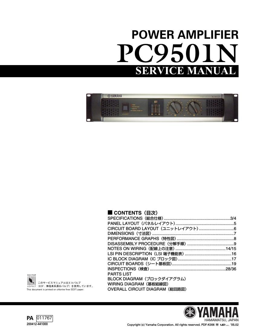
Yamaha pc9501 n

This is the 72 pages manual for yamaha pc9501 n.
Read or download the pdf for free. If you want to contribute, please mail your pdfs to info@audioservicemanuals.com.

Page: 1 / 72
left right
yamaha pc9501 n

Extracted text from yamaha pc9501 n (Ocr-read)


Page 1

PC9501N 2 * This applies only to products distributed by YAMAHA KEMBLE MUSIC (U.K.) LTD. IMPORTANT NOTICE This manual has been provided for the use of authorized Yam aha Retailers and their service personnel. It has been assumed that basic service procedures inherent to the industry , and more specifically Yamaha Products, ar e already known and understood by the users, and have therefore not been restated. WARNING : Failure to follow appropriate service and safety procedures when servicing this product may result in personal injury, destruction of expensive components and fa ilure of the product to perform as specified. For these reasons, we advise all Yamaha product owners that all serv ice required should be performed by an authorized Yamaha Retailer or the appointed service representative. IMPORTANT : This presentation or sale of this m anual to any individual or firm does no t constitute authorization certification, recognition of any applicable techni cal capabilities, or establish a principal-agent re lationship of any form. The data provided is believed to be accurate and applicable to the unit(s) indicated on the cover. The research engineering, an d service departments of Yamaha are continually stri ving to improve Yamaha products. Modification s are, therefore, inevitable and changes in specification are subject to change without notice or obligation to retrofi t. Should any discrepancy appear to exist, please contact the distributors Service Division. WARNING : Static discharges can destr oy expensive components. Disc harge any static electricity your body may have accumulated by grounding yourself to the ground bus in the unit (heavy gauge black wires connect to this bus). IMPORTANT : Turn the unit OFF during disassembly and parts replacement. Recheck all work before you apply power to the unit. WARNING: CHEMICAL CONTENT NOTICE! The solder used in the production of this product contains LEAD. In addition, other electrical/electronic and/or plastic (Where applicable) components may also contain traces of chemicals found by the Ca lifornia Health and Welfare Agency (and possibly other entities) to cause cancer and/or bi rth defects or other reproductive harm. DO NOT PLACE SOLDER, ELECTRICAL/ELECTRONIC OR PLAST IC COMPONENTS IN YOUR MOUTH FOR ANY REASON WHAT SO EVER! Avoid prolonged, unprotected contact between sol der and your skin! When soldering, do not inhale solder fumes or expose eyes to solder/flux vapor! If you come in contact with solder or components located insi de the enclosure of this product, wash your hands before handling food. WARNING: THIS APPARATUS MUST BE EARTHED IMPORTANT THE WIRES IN THIS MAINS LEAD ARE COLOURED IN ACCORDANCE WITH THE FOLLOWING CODE: GREEN-AND-YELLOW : EARTH BLUE : NEUTRAL BROWN : LIVE As the colours of the wires in the mains lead of this apparatus may not correspond with the col oured markings identifying the terminals in your plug, proceed as follows: The wire which is coloured GREEN and YELLOW must be connected to the terminal in t he plug which is marked by the letter E or by the safety earth symbol or coloured GREEN and YELLOW. The wire which is coloured BLUE must be connected to the terminal which is marked with the letter N or coloured BLACK. The wire which is coloured BROWN must be connected to the terminal which is marked with the letter L or coloured RED. -– WARNING Components having special characteristics are marked and must be replaced with parts having specification equal to those originally installed. å°ã®å•†å“ã¯ã- 安全 ã‚’ 維æŒã™ ã‚‹ 㟠ã‚ã«é‡è¦ãªéƒ¨å“ã§ã™ã-‚ 交 æ›ã™ ã‚‹ å ´åˆã¯ã-安全㮠㟠゠ã«å¿…ãšæŒ‡å®šã®éƒ¨å“ ã‚’ ã- 使ç-¨ ã ã  ã• ã„ã-‚

Page 2

PC9501N 3 -– SPECIFICATIONS Power output level (Rated power) 120 V (U, V, T)/240 V (A) 230 V (H, B, W, K, O) 1 kHz, THD+N=1 % 8 -„¦/STEREO 1000 W x 2 1050 W x 2 4 -„¦/STEREO 1600 W x 2 1650 W x 2 8 -„¦/BRIDGE 3200 W 3300 W 20 Hz-20 kHz, THD+N=0.1 % 8 -„¦/STEREO 925 W x 2 950 W x 2 4 -„¦/STEREO 1400 W x 2 1500 W x 2 8 -„¦/BRIDGE 2800 W 3000 W 1 kHz, 20 mS nonclip 2 -„¦/STEREO 2300 W x 2 2300 W x 2 4 -„¦/BRIDGE 4600 W 4600 W Power bandwidth 10 Hz-40 kHz (THD+N=0.5 %) Half power Total harmonic distortion (THD+N) -‰¤0.1 % 20 Hz-20 kHz, Half power Frequency response MAX 0 dB RL=8 -„¦, Po=1 W, TYP 0 dB f=20 Hz-50 kHz MIN -“1 dB Intermodulation distortion (IMD) -‰¤0.1 % 60 Hz:7 kHz, 4:1, Half power Channel separation -‰¥70 dB Half power, RL=8 -„¦, 1 kHz, Vol. max., Input 600 -„¦ shunt Residual noise -‰¥-“70 dBu Vol. min., 20 Hz-20 kHz (DIN AUDIO) SN ratio 106 dB 20 Hz-20 kHz (DIN AUDIO) Damping factor -‰¥800 RL=8 -„¦, f=1 kHz Sensitivity +9 dBu Vol. max., Rated power into 8 -„¦ Voltage gain TYP 32 dB Vol. max. Maximum input voltage MIN +22 dBu Input impedance TYP 20 k -„¦/Balanced, 10 k -„¦/Unbalanced Controls Front panel POWER switch (ON/OFF) Volume (31 positions) /ch Rear panel MODE switch (STEREO/BRIDGE/PARALLEL) HPF switch (ON/OFF) /ch fc=20 Hz 12 dB/octave DIP switch (6P) Connectors Input XLR-3-31 type /ch Euroblock connector (balance) /ch Output SPEKON /ch, 5-way binding posts Network RJ45 x 2 Power AC inlet Indicators POWER/STAND-BY Green/Orange PROTECTION Red TEMP Red (heatsink temp -‰¥85°C) REMOTE Green Level meters 10 points LED meter /ch Load protection POWER switch ON muting, DC detection Amp. protection Temp. detection (heatsink temp -‰¥90°C), VI limiter (RL -‰¤1 -„¦) Limiter Comp.: THD -‰¥0.5 % Cooling Dual variable-speed fan Power requirements U, V, T 120 V, 60 Hz H, B, W, K, O 230 V, 50/60 Hz A 240 V, 50/60 Hz Power consumption Idling 55 W Output power, 4 -„¦750 W (U, V, T)/1000 W (A) 1100 W (H, B, W, K, O) Dimensions (W x H x D) 480 x 88 x 456 mm Weight 13 kg Accessories Power cord, Security cover, Owners manual, 3-pin Euroblock connector x 2 0 dBu=0.775 Vrms, Half power=1/2 Output power (3 dB below rated power)