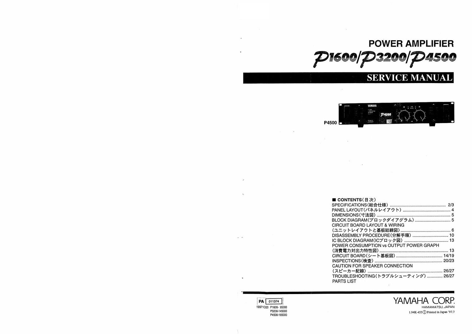
Yamaha p1600 p3200 p4500

This is the 42 pages manual for yamaha p1600 p3200 p4500.
Read or download the pdf for free. If you want to contribute, please mail your pdfs to info@audioservicemanuals.com.

Page: 1 / 42
left right
yamaha p1600 p3200 p4500

Extracted text from yamaha p1600 p3200 p4500 (Ocr-read)


Page 1

POWER AMPLIFIER

I CONTENTS( E 291)

SPEC!F|CAT|ONS(¥5-1%&*§) ...................... .. 2/3

PANEL LAYOUT(/\':?~)w4 7 '7 h) ...... 4
DIMENSIONSMSEE) ................................. .. 5
BLOCK DIAGRAM<7EI /057'4705A) .............................. 5
CIRCUIT BOARD LAYOUT & WIRING
(12v #12476 htgflififil) .......................................... 6

7 , DISASSEMBLY PROCEDURE<fi§¥JIE> 10
IC BLOCK DIAGRAM POWER CONSUMPTION vs OUTPUT POWER GRAPH
(ifififihmflhfitm) ............... 13
CIRCUIT BOARD(-/- #5115121). 14/19
INSPECTIONSOfiE) ......................................................... 20/23
CAUTION FOR SPEAKER CONNECTION
(z 6-): 4m) ............................................................... 26/27
TROUBLESHOOTING< I~ 57»9 1-7-4 >0) ............. 26/27
PARTS LIST

'-

W -I YAMAHA CORP.
19971020 P1600 95000 HAMAMATSU.JAPAN
PSZOCLMSOOO

1.94K-4 5 V l ' I an'97.7
moo-165000 5 ®Pm°dm 3*

Page 2

P1EOOIP3200IP4500

IMPORTANT NOTICE

This manual has been provided tor the use of authorized Yamaha Retailers and their service personnel it
has been assurneti that bask: service procedures inherent to the industry, and more specifically Yamaha
Products. are already known and understood by the users. and have therefore not been restated

WARNING: Farlure to follow appropriate service and safety procedures when servicing this product
may result in personal injury, destruction or expensive components and laiiure of the
product to periorm as specified. For these reasons, we advise all Yamaha product
owners that all service required should be performed by an authorized Yamaha Retailer
or the appointed service representative.

IMPORTANT: The presentation or sale of this manual to any individual or firm does not constitute
authorization, certification, recognition at any applicable technical capabilities, or establish
a principal-agent relationship or any forth.

The data provided is believed to be accurate and applicable to the unit(s) indicated on the cover. The
research. engineering. and service departments at Yamaha are continually striving to improve Yamaha
products. Modifications are, therefore. inevitable and changes in specification are subiect to change
without notice or obligation to retrofit. Should any discrepancy appear to exist. please contact the dis-
tributors Service Division.

WARNING: Static discharges can destroy expensive components. Discharge any static electricity
your hndy may have accumulated by grounding yoursell to the ground bass in the unit
(heavy gauge black wires connect to this buss).

IMPORTANT: Turn the unit OFF during disassembly and parts replacement. Recheck a_ll work before
you appty power to the unit.

WARNING: CHEMICAL CONTENT NOTICE!

The solder used in the production of this product contains LEAD. in addition, other electrical/electronic
and/or plastic (where applicable) components may also contain traces of chemicals found by the Calilomia
Health and Welfare Agency (and possibly other entities) to cause cancer and/or birth detects or other
reproductive harm.

DO NOT PLACE SOLDEH, ELECTRICAL/ELECTRONIC OR PLASTIC COMPONENTS IN YOUFI
MOUTH FOR ANY REASON WHAT SO EVEHI

Avoid prolonged, unprotected contact between solder and your skin! When soldering. do not inhale solder
fumes or expose eyes to solder/flux vapor!

If you come in contact with solder or components located inside the enclosure of this product, wash your
hands before handling food.

I WARNING
Components having special characteristics are marked A and must be replaced with pans having
specification equal to those originally installed

1 A 5110555, iff':§ti$¢£7;blilgxflrfii1fc Zififbllyéliy §E207;i)rZ-f?§ii7>flfl%:l'EIHTiSLa

I SPECIFICATIONS

0 General Specifications P4500, P3200, P1600

PI SOOIPSZDOIFMSOO

P4500 P3200 P1600

Power Output Level (Hated Power) art/STEREO

460W+460W 340W+340W 160W+160W

20 Hz-20 kHI 40/STEREO 620 W + 620 W 0 W + 440 W 200 W 4, 200 W
0.05% Bil/BRIDGE 1240 W 880 W 400 W
1 kHz SKI/STEREO 520 W + 520 W 370 W o 370 W 175 W e I75 W
0.05% WSTEREO 720 W + 720 W 520 W o 520 W 230 W 4- 230 W
SKI/BRIDGE 144OW 1040W 460W
1 kHz, 20 ms, no clip ZWSTEREO 1300W¢1300W 550W+950W 350W+350W
Power Bandwidth Hall Power, 0.1% 10 HZ~40 kHz
Total Harmonic Distortion (THD 4» N) 4-BWSTEREO O 05%
20 Hz~20 kHz. Hail Power BIT/BRIDGE
Frequency Response 10 Hz-50 kHz, 40. -1 d3
inlermoduletion distortion (IMD) hart/STEREO 0 05%
7 kHz: 60 Hz. I: 4. Hell Power SKI/BRIDGE '
Damping factor 1 kHz, an 200
input Impedance 30 kit/Balance, r5 kit/Unbalanced
Residual Noise Vol. min. 12.7 kHz LPF
IHF-A network 4° dB
SN Ratio Input 6000 shunt 12] kHz LFF
lHF-A network 105 dB 104 dB 101 dB
Channel Separation Hail Power, an. Vol. max 65 dB, 20 Hz-ZO kHz
input 600!) shunt 75 dB. 1 kHz
Slew Rate STEREO >30 V/u sec
SQ lull swing BRIDGE >50 V/u sec
Sensrtivity (Vol. max.) Rated Power into on +5.7 dB I +42 dB 1 n2 dB
Voltage Gain (Vol. maxi) 32.1 dB

Controls Front Panel POWER switch (Push oanush olf)
Volume (31 position dB calibrated)
Rear Panel Mode switch (STEREO/BRIDGE/PARALLEL)
Connectors Input Barrier strip terminal
XLR-a-ar type
1/4-irlch phone jack (balanced)
Output 5-way binding posts
Indicators POWER
TEMP (heatsink lamp 2 65%)
PROTECTION (mute)
CLIP X 2
OUTPUT SIGNAL x 2

Protectron Circuits

POWER switch ONIOFF, Muting. DC detectlon
TEMP (heatsink temp 2 95°C)

PC limiter RL S In
Fen Circuits Low speed (50°C), Variable, High speed (70"C)
Power Requirements United States a Canada 120 V. so Hz

Europe 230 v, so Hz

Other 240 V. 50 Hz

Power Consumption

500 wreso VA | 400 W/500 VA | zoo wrzso VA

Dimensions (W x H x D)

480 X 103.5 x 455 mm

Weight 16 kg l 15 kg 1 12 kg
Accessories Security cover
Options Ventilation panel; VPi

0 dB=0,77S Vrms, Halt Power=1l2 Power Output Level (Rated Power)