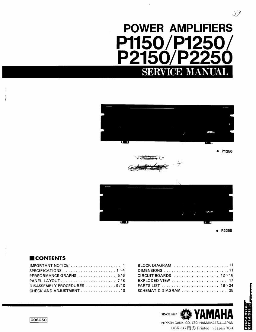
Yamaha p1150 P1250 P2150 P2250

This is the 21 pages manual for yamaha p1150 P1250 P2150 P2250.
Read or download the pdf for free. If you want to contribute, please mail your pdfs to info@audioservicemanuals.com.

Page: 1 / 21
left right
yamaha p1150 P1250 P2150 P2250

Extracted text from yamaha p1150 P1250 P2150 P2250 (Ocr-read)


Page 1

<72
POWER AMPLIFIERS

P1150/P1250/

P2150/ P2250

MAMA

I P1250

mm:


o P2250
- CONTENTS

IMPORTANT NOTICE ................... 1 BLOCK DIAGRAM ...................... 11
SPECIFICATIONS .................... 1~4 DIMENSIONS ......................... 11
PERFORMANCE GRAPHS ............... 5/6 CIRCUIT BOARDS .................. 12~16
PANEL LAYOUT ...................... 7/8 EXPLODED VIEW ...................... I7
DISASSEMBLY PROCEDURES ............ 9/10 PARTS LIST ....................... 18~24
CHECK AND ADJUSTMENT ................ 10 SCHEMATIC DIAGRAM .................. 25

'V '0

2. 2.

SINCE I887 YAMAHA 56:

3:

NIPPON GAKKI CO LTD. HAMAMATSU, JAPAN a :

1,53K~845 IEI] (X3 Primed in Japan '854 OD

Page 2

P1150/P1250/P2150/P2250

( IMPORTA T NOTICE

l This manual has been provided for the use of authorized Yamaha Remlcrs and their service personnel.
II has been assumed that basic servicc proccdurcs inherent to the industry, and more specifically Yamaha
Products, are already known and understood by the users, and have therefore not been rcstated.

l WARNING: Failure to follow a
l

pproptiatc service and carety procedures when scnicing this product

may result in personal lniury, dcstruction of Expensive components and failure of the

product to perform

as spemiicd. For these reasons, we advise all Yamaha product owners

that all service required should be pctformcd by an authorized Yamaha Retailer or the

appointcd service representative.

l IMPORTANT: The presentation or salt or this manual to any intinitluai or iitrn does not constitute
authorization, certification, recognition of any applicable technical capabilities, or
:stabllsh t principle-agent rtiauontnip of any form

The data pr am is believed to be
research, engtn

accurate and applicable to the unit(s) indicatad an the cover. The

ring, and service departments of Yamaha are continually stritlng to improic Yamaha

products, Modifications are, therefore, inetitablc and changes in specification arc subitct to change Without
notice or obligation to rctroiit Should an» discrepant» appear to exist, please contart the distributor's

Service DWISIOII

WARNING: static discharges can desttm expcnsnc compomms Discharge int stall: clcCttIClI) tour
r bod» may irate accumulated by grounding yourself to the ground buss in the unit [heaw
gauge black wires conncct to this buss),

IMPORTANT: Turn the unit OFF

you apply power to

during disassembl) and parts replacement RecheckLkurk before
the unit.

.SPECIFICAIIONS

P11 0

Output Power Spots meet

OUTPUT SPECIFICATIONS J
r

60Hl&7kH14:1
Pomr Bandwidth (6 THD 50.1%)

no prccnnditioning crit-ria 3 ohms l 4 ohms
.20Hz - zoItHz l 1kHz lzoI-iz - zottHx l 1km

. . r .

Continuum ll 0 wave output power l
.atlnsthlnotOSXTHD 100 1 "5 r 150 l 165'
Total Harmonic Distortion (THD) 5 0.007% l 30.00396 S 0.01% S 0.005% 1
@55w ; @ssw l @75w l @75w

intuitnoduiation Distortion (IHDI 30.00% @ 55 w 50.01% @ 75 w ;

10Hzto100kHz©55W l IOHztoIDOkHZ®75W¥

Froqunncy Romans. [1 watt output)

+o,-1 dB, 10 Hz to 50 kHz

Dumping Fuctur

2110®1ltHz 255®1kHz i

Slaw Rat-

150 volts/microsecond tull swmg

SinmI-to-Noiso (Input than)

>110ua, -6 dB/octaw LPF @1247 kHz
2115 dB, lHF-A network

Residual Noin
(Input AYT 6 minimum)

Input Impedance

S-sousm, -s dB/Octav! LPF @1147 kHz
3-90 dBm, lHFrA network

l 215 kohrns, balanced or unbalanced (ATT @ max) i
i

SInsi vity +4 dBm (1.23 V rms) for nominal output 14 ohm Inad)
Volt-go Gain 26.0 dB
Signal: Green LED turns on when signal present at output
is at or above 2 volts RMS [20 Hz # 20 kHz).
indie-tors Cllppmg: Red LED turns on when THD 21%.

Protection: Red LED turns on when protection or muting IS on. .
Pilot: Red LED turns on when power is on

Protlct'mn Circuits

Muting: Output muted 5 seconds (:2 sec t after power is on.
DC sense: Output shut off if 12V DC sensed goutput.
Thermal: Output shut off if heat sink temp _35 degrees C.
Current i
Limiter: Output reduced if loadgz ohms.

Fan Circuit

Controls

Pomr Requirements

Fan is normallv at low speed; when heat sink reaches 60 degrees l
Centigrade, fan goes to high speed; than resets to low at 45°C.
Front: 32 step Input Attenuator; O to -20 dB in 1 dB steps,
-20 to 30 dB In 2 dB steps, then -33, -37, #42, -50, -60
dB, and infinite attenuation.

Push On/Push 0" POWER SWItch, l
105 - 130 volts, 50 or 60 Hz, AC, 250 W (300 VA)

Weiaht 28.6 lbs l13 kg) l
Dimlnsions width: 18~7l3 inches (480 mm)
l Height: 5-1/4 inches (132 mm) l
. Overall Depth: 16-3/4 Inches (423 mm)
l Depth Behind Front Panel: 15-1/8 inches (384 mm) l
Accessory

setting of input attenuator (included).

Rubber cap to discourage unauthorized or accidental changes :5