Yamaha pm1000 e

This is the 20 pages manual for yamaha pm1000 e.
Read or download the pdf for free. If you want to contribute, please mail your pdfs to info@audioservicemanuals.com.

Page: 1 / 20
left right
yamaha pm1000 e

Extracted text from yamaha pm1000 e (Ocr-read)


Page 1

HOW TO USE
THE CONSOLE

NOTE: The information presented in the following
section of the manual complements the basic feature
callouts in Section 1, ln some cases, those callouts pro-
vide sufficient information, so the feature has not been
included in this section.

INPUT MODULE

PHASE SWITCH

When two or more mics are receiving the same pro-
gram source (or one mic is receiving leakage from the
source intended for another mic) an aut-of-phase con-
dition may cause acoustic phasing cancellations that will
be most noticeable in the low frequencies. To check
inputs for correct phase, begin with all channels in the
N mode. Assign mics 1 and 2 to the cue bus, placing the
microphones close together and near a sound source
that contains appreciable bass. Using Input Level,
match the level of the two microphones. Then, listening
to the blend of the two inputs in the cue headphones,
reverse the phase of mic 2 by moving its phase switch
to R. If the bass increases, leave the switch in R mode,
and if the bass decreases, return the switch to N. This
establishes an in-phase condition between mics 1 and 2.
Repeat the procedure for mics 1 and 3, 1 and 4, and so
forth until all inputs have been compared to mic 1. Line
inputs may be checked in a similar fashion, listening for
a decrease or increase in the bass content of the program.
The absolute phase of an input is not significant, so long
as the inputs are in phase with each other. Any input
can serve as the "normal" or reference input.

Once the inputs are set up in phase, it may be desir-
able to intentionally reverse the phase of certain
channels. Where numerous microphones are in close
proximity, especially with drum sets, reversing the phase
of adjacent mics can significantly improve the sound.
The potential improvement is due to the time delay in
the sound reaching two mics, a delay which causes fre-
quency-dependent phase cancellations. These cancella-

S

tions are heard as an overall muddy character, and

reversing the phase of one microphone may improve the
sound by altering the frequencies at which cancellation
occurs. When time permits, each input may be examined
to hear whether reversing the phase will improve the
overall sound character of the mix. This should be done
after the initial set up, during the sound check. Listen-
ing is the only valid means to determine the best phase
setting, and meters are not likely to help. What sounds
best is best, except when the program is being moni-
tored with two or more channels and is being recorded
in a format with fewer channels.

If, for example, a stereo live mix sounds good, but a
monaural mix is being recorded, the monaural output
should be examined to determine whether the reversal of
one or more channels' phase switches will improve the
mix. The stereo monitor can sound acceptable due to
acoustic delays that tend to correct out»of»phase signals,
whereas the same signals, when mixed together, cancel
to a greater degree.

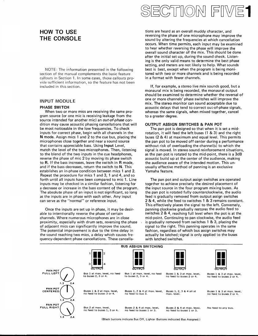
OUTPUT ASSIGN SWITCHES & PAN PDT

The pan pot is designed so that when it is set a mid-
rotation, it will feed the left buses (l & 3) and the right
buses (2 & 4) at maximum and equal level. This permits
the pan pot to be moved off center during a performance
without risk of overloading the channel(s) to which the
signal is moved. In stereo sound reinforcement situations,
as the pan pot is rotated to the mid-point, there is a BdB
acoustic build up at the center of the audience, making
the audience aware of the intended motion. This un-
usually effective method of panning is an exclusive
Yamaha feature.

The pan pot and output assign switches are operated
together to achieve precisely the desired placement of
the input source in the four program mixing buses. As
the pan pot is rotated fully counterclockwise, the audio
feed is gradually removed from output assign switches
2 & 4, while the feed to switches 1 & 3 remains constant.
This effectively places the signal to the left. Conversely,
panning clockwise gradually restores the audio feed to
switches 2 8t 4, reaching full level when the pot is at the
mid-point. Continuing to pan clockwise, the audio feed
is gradually removed from switches 1 & 3, placing the
signal to the right. This panning operates in the same
fashion, regardless of which bus assign switches may
actually be Iatched;signa| is only applied to the buses
with latched switches.

BUS ASSIGN SWITCHING

3
PAN POT UT?
FULL LEFT Bus 1 at max. level, no feed Bus 1 at max. level, no feed
to buses 2. 3 or 4. to buses 2, 3 or 4.
L: 2.4
PAN POT
CENTERED Buses 1 a 2 at max. level, Buses 1. 2 a 4 at max. level.
"0 feed to buses 3 or 4. no feed to bus 3.
L3 2A
PAN POT
ruu. RIGHT Bus 2 at max. level, Buses 2 a. 4 at max. level,
no load to buses 1, 3 or 4. no feed to buses 1 or 3.
1.3 2.4

UTPU

OUTPUT

Buses 1 & 3 at max. IeVeI,
no feed (a buses 2 or 4.

Buses 1 st 3 at max. level,
no feed to buses 2 or A.

Buses 1, 2, 3 a A all at
max. level.

Buses 1 a 3 at max. leval,
"0 feed to buses 2 or 4.

Buses 2 a 4 at max. level,
no feed to buses 1 or 3.

NO feed to any bus.

(Black buttons indicate Bus Off, Lighter Buttons indicated Eus Assigned.)

Page 2

FWEZ

ECHO 1 8i 2 MIX CONTROLS

The audio level applied to the echo mixing buses is
assigned with these controls. In sound reinforcement,
where the echo outputs usually drive stage monitor
(foldback) amplifiers, these controls become foldback
mix controls. Since the buses are fed with pre-fader, post-
equalizer audio, performers are not distracted by pro-
gram level adjustments.

HIGH PASS FILTER

The filter should nearly always be switched on at
40Hz, If no effect is noticed, it should be left on. 40Hz
reduces subsonic signals from turn-on transients (and
from warped records). It is also useful in reducing low
frequency standing waves. These are acoustic resonances
that occur in small rooms, like studios and smaller clubs.
Standing waves will crosstalk into all microphones,
creating a severe problem that baffles cannot cure. (In
large rooms, the waves are sufficiently low in frequency
that they are not a problem, and outdoors they do not
occur.)

The BOHZ setting reduces vocal P-pops. lt also reduces
60Hz hum from electric instruments without noticeably
changing the sound (except perhaps on the lowest organ
or bass notes.) If switching the 80Hz filter it has no
audible effect, it should be left on; it is generally desir-
able to attenuate unused frequency response. This
reduces noise. What is more, the lowest frequencies are
not optimum for speech reinforcement purposes; they
interfere with speech intelligibility, cause boominess to
be accentuated, and waste amplifier power. The 80H:
filter cuts down on these deleterious effects without
substantially altering the character of the mix.

FILTER CURVES

soc

g / / \
: .z~ .

s

, s q

.5

N /

m .w m .K a m m
EQUALIZER

Equalizers are similar to tone controls", but they
serve a somewhat different purpose. Certainly, an
equalizer can be used to enhance the sound of a given
instrument or vocal, as well as an entire mix._.often
this is all that the equalizer does. However, equalizers
can also be used to create a unique acoustic space" for
each type of instrument when instruments and vocals are
mixed together. This is especially important when the
sound sources share similar frequency ranges, thereby
partially masking one another. By carefully tuning each
input's equalizer to emphasize the dominant frequency
range of the individual sound sources, there is less
competition" between the sources, hence less masking.
This use of equalization not only enhances the sound of
each instrument, it also tends to increase the apparent
separation between channels, thereby improvingthe mix.

As an example of the concept iust stated, consider
two similar instruments, miked on separate inputs, and
mixed onto the same program bus. A guitar and a bass,
both boosted at 2kHz, will mix together in such a way
that many of the notes will be indistinct; listeners may
not be sure where one instrument leaves off and the
other begins. If instead, the guitar is peaked at 4kHz,
and the bass at 1kHz, then the two instruments will be
easier to hear. The apparent loudness of the music may
actually increase, although there is really no change
in the overall power levels,

A related use of equalization is for the reduction of
acoustic crosstalk (leakage). This is done by rolling off
portions of the frequency spectrum that are not utilized
by a particular input source. For instance, a bass drum
and trumpet may be leaking into each other's micro-
phones. The two instruments are played at loud levels,
and physical separation cannot be made sufficient to
cure the crosstalk. In this case, the Bass on the trumpets
equalizer should be reduced, and the Treble on the
drum's equalizer should be reduced until the best sound
is obtained. This type of equalization filters the leakage
components without significantly affecting the character
of each instrument in its own channel.

The PM-1000 channel equalizers provide low and high
frequency shelving and mid-range peaking...both boost
and cut. The distinction between the Mid-Flange peaking
and the Bass and Treble shelving curves can be under-
stood by examining the diagram below. Observe the
peaking curve for a 1kHz setting of the Mid-Range Select
switch; as the frequency rises toward 1kHz, the amount
of equalization increases. Then, as the frequency
continues to rise past 1kHz, the amount of equalization
decreases, but at 1kHz, the effect is maximum (boost or
cut, depending on the rotation of the Mid-Range control).
If the Mid-Range switch is moved to 2kHz, then the
maximum effect occurs at 2kHz, and a 4kHz setting of
the switch provides maximum boost or cut at 4kHz.
Observe, too, that while the mid-range peak frequency
may be a 1,2 or 4kHz, a wide envelope of frequencies
are acutally equalized (light shading on diagram). This
is peaking equalization.

EQUALIZER CURVES

almlql ill n. c

Jillil-RA \lGE j"

MAX.
BOOST

do

7\/<\\(
2

Ram n... ma

54 MAX.
cuT

20 Inc an IX sr. m m
Fromm m m