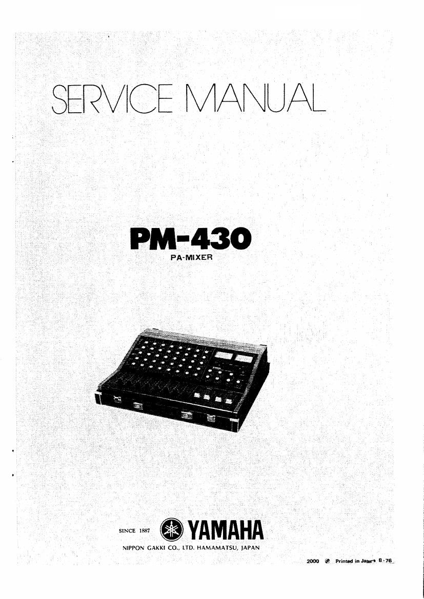
Yamaha pm 430 service manual

This is the 30 pages manual for yamaha pm 430 service manual.
Read or download the pdf for free. If you want to contribute, please mail your pdfs to info@audioservicemanuals.com.

Page: 1 / 30
left right
yamaha pm 430 service manual

Extracted text from yamaha pm 430 service manual (Ocr-read)


Page 2

PM-430-(S/F1021~ )

CONTENTS
Removing the Unit .......................................................... 1
General Specifications ........................................................ 2
Comm! Panel Operations ........... I: j ....................................... 3
Rear 9ane| Operations ....................................... 4
Schematic Diagram ........................................................ 5
Power Circuit Arrangements ................................................... 7
Block Diagram & Leve! Diagram ................................................. 8
Check and Adjustment Specifications ............................................ 9
Respective Printed Circuit Boards
1, CF Circuig Board ........................ _ ............................ 12
2. PA Circuit Board ................. 32
3. PA-SW Circuit Board .................................................... 12
4. MP Circuit Board ................................................... 13
5. AUX C-‚¬rcuit Board .................................................... 13
6. HP Circuit Board .................................................... 13
7V HP-SW Circuit Board .................................................... 13
8. LED Circuit Board ................................................... I4
9. OSW Circuit Board .................................................. M
10. HIN Circuit Board ..................................................... 14
H, BP Circuit Board ...................................................... l5
12 PS Circuit Board ...................................................... E6
REMOVING THE PIA-430 UNIT
1. Remove the 2 mounting screw located or: the back 2, Raise the control pane! porton as shown By the
of the unit. arrow and lock in upright position by means of the

hinge on the right side of the unit.