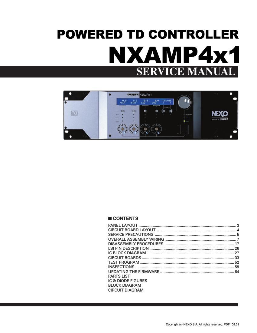
This is the 123 pages manual for yamaha nxamp 4x1 power amp service manual. Read or download the pdf for free.
If you want to contribute, please mail your pdfs to info@audioservicemanuals.com.
Page: 1 / 123
Extracted text from yamaha nxamp 4x1 power amp service manual (Ocr-read)
Page 1
NXAMP4x1
2
WARNING
Components having special characteristics are marked and must be replaced with parts having specification equal to those originally
installed.
IMPORTANT NOTICE FOR THE UNITED KINGDOM
Connecting the Plug and Cord
WARNING:THIS APPARATUS MUST BE EARTHED
IMPORTANT.The wires in this mains lead are coloured in accordance with the following code:
GREEN-AND-YELLOW: EARTH
BLUE: NEUTRAL
BROWN: LIVE
As the colours of the wires in the mains lead of this apparatus may not correspond with the coloured markings identifying the terminals in your
plug, proceed as follows:
The wire which is coloured GREEN and YELLOW must be connected to the terminal in the plug which is marked by the letter E or by the safety
earth symbol
or colored GREEN or colored GREEN and YELLOW.
The wire which is coloured BLUE must be connected to the terminal which is marked with the letter N or coloured BLACK.
The wire which is coloured BROWN must be connected to the terminal which is marked with the letter L or coloured RED.
WARNING: This product contains chemicals known to the State of California to cause cancer, or birth defects or other reproductive harm.
DO NOT PLACE SOLDER, ELECTRICAL/ELECTRONIC OR PLASTIC COMPONENTS IN YOUR MOUTH FOR ANY REASON WHAT SO
EVER!
Avoid prolonged, unprotected contact between solder and your skin! When soldering, do not inhale solder fumes or expose eyes to solder/flux
vapor!
If you come in contact with solder or components located inside the enclosure of this product, wash your hands before handling food.
Page 2
NXAMP4x1
3 - Rear Panel
PANEL LAYOUT
1Power switch
2Amplifier indicators
3LCD display
4Encoder
5Navigation buttons (A & B)
6Volume indicators
1Mains connectors
2Balanced audio inputs with link
3Expansion slot
4Power outputs
- Front Panel
A 0 2 1 6 7 5 3 4 8 9
6 5 7 3 2 4 1
7Mute buttons
8Select buttons
9Channel indicators
0Air intakes
AScrew holes for handles
5RS-232 Firmware update port
6GPIO port
7Rear end mounting holes