Yamaha nx sw100

This is the 144 pages manual for yamaha nx sw100.
Read or download the pdf for free. If you want to contribute, please mail your pdfs to info@audioservicemanuals.com.

Page: 1 / 144
left right
yamaha nx sw100

Extracted text from yamaha nx sw100 (Ocr-read)


Page 1

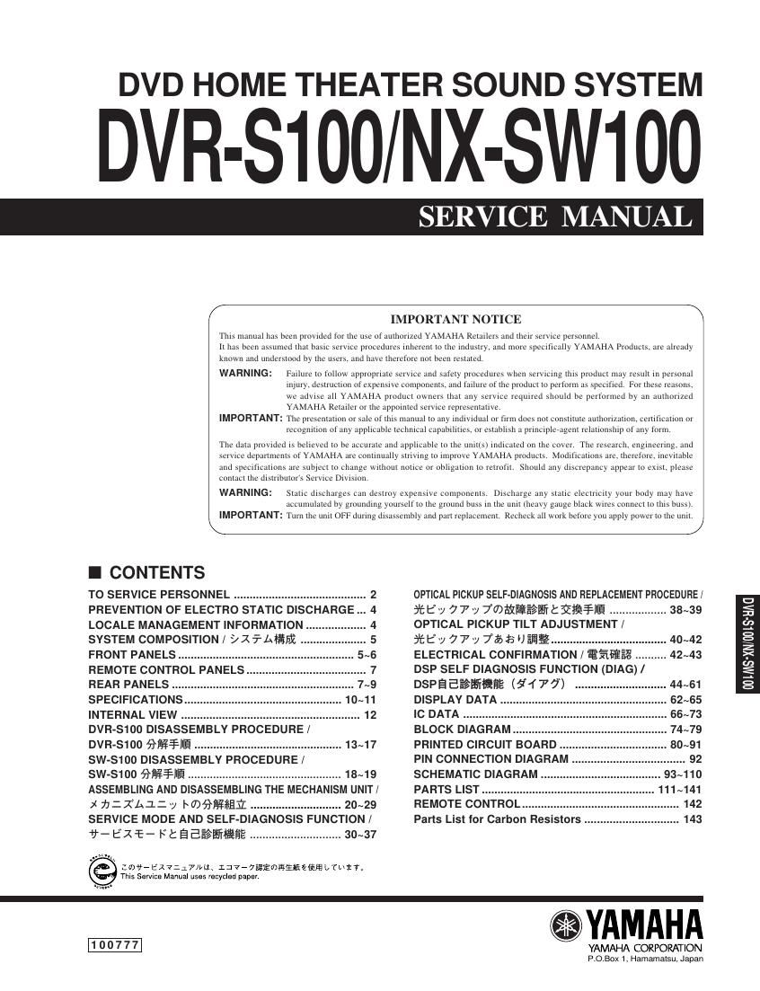
DVD HOME THEATER SOUND SYSTEM

DVR-S100 NX-SW100

SER E MANU

IMPORTANT NOTICE

This manual has been provided for the rise of authorized YAMAHA Retailers and rlieir Service personnel,
It has been assumed thar basic service procedures inherent to the industry. and more specifically YAMAHA Products. are already
known and understood by riie users. and have therefore not been resiared.


WARNING: Failure to follow appropriare service and sateiy procedures when seri icing this producl may result in personal
injury. destrucrion of expensive components. and failure of the product to perform as specified, For these reasons.
we advise all YAMAHA product owners that any service required should be performed by an authorized
YAMAHA Retailer or the appointed service represeuratiye,

IMPORTANT: The presenration or sale of iiiis manual to any individual or firm does nol consiituie authorization. cerriticarion or
I'ecogniiion of any applicable technical capabilities. or establish a princxplerageni relarionshrp of any form

The data provided is believed to be accurate and applicable to Ihe unirrs) indicared on the cover. The research eugmeering. and
service departments of YAMAHA are conlinually striving to improve YAMAHA products. Modifications are, Iherefore, inevitable
and specifications are subject Io change wilhoiit notice or obiigarion to retrofit. Should any discrepancy appear ro exist. please
contact The distributor's Service Division.
WARNING: Static discharges can destroy expensive components, Discharge any static electricity your body may have

accumulated by grounding yourselt to the ground buss in the unit (hem) gauge black wii-es connecr to this buss).
IMPORTANT: Turn the unit OFF during disassembiy and part replacement, Reclieck all work before you apply power to The unir

I CONTENTS

TO SERVICE PERSONNEL .......................................... 2
PREVENTION OF ELECTRO STATIC DISCHARGE 4
LOCALE MANAGEMENT INFORMATION
SYSTEM COMPOSITION / 9 X % area:

FRONT PANELS ......................
REMOTE CONTROL PANELS 7
REAR PANELS ........... 7~9
SPECIFICATIONS. .. 10~11
INTERNAL VIEW ......................................................... 12
DVR-S1oo DISASSEMBLV PROCEDURE /

DVR-S1oo METIIIE ............................................... 13~17
sw-S1oo DISASSEMBLY PROCEDURE/

SW-S1OO Wiring ................................................. 13~19
ASSEMBLING AND DISASSEMBLING THE MECHANISM UNIT/
x 7;:XLi11y hwfifigrfifi ............................. 20~29
SERVICE MODE AND SELF-DIAGNOSIS FUNCTION /
fieexrce Ftaaéalifiifidg ............................. 30~37

' Lowe EXT/:17ma. 1:777igiwfiiifiéfififi LTLIST.
ThtS Service Manuai uses Iecycied paper

OPTICAL PICKUP SELF-DIAGNOSIS AND REPLACEMENT PHOCEDURE/
fi'fiE y 77 v Twaiieeelifitimime .................. 38~39
OPTICAL PICKUP TILT ADJUSTMENT/

*5? 777 7HEBEUEJ§1¥ .............
ELECTRICAL CONFIRMATION / Eskimo .......... 4243
DSP SELF DIAGNOSIS FUNCTION (DIAG) /

DSP a Eéafliiififie (5i 1 7 7)

DISPLAY DATA .......................

IC DATA ................

BLOCK DIAGRAM

PRINTED CIRCUIT BOARD

PIN CONNECTION DIAGRAM 92
SCHEMATIC DIAGRAM . 93~110
PARTS LIST ................. . 111~141
REMOTE CONTROL ................... .. 142

Parts List for Carbon Resistors .. 143

YAMAHA

YAMAHA CORPORATION
P.0.Box 1, Hamamatsu, Japan

Page 2

DVR-S100/NX-SW1OO

I TO SERVICE PERSONNEL AC LEAKAGE
WALL EQUIPMENT TESTER OR
C.ritical Components Information OUTLET UNDER TEST EQUIVALENT
Components having special characteristics are marked l
and must be replaced with parts having specifications equal
to those originally installed. ® :ID-
2. Leakage Current Measurement (For 120V Models Only) J_-

When service has been completed, it is imperative to verify

that all exposed conductive surfaces are properly insulated INSTLfléoE-ENG
from supply circuits.
0 Meter impedance should be equivalent to 1500 ohm shunted ° Leakage current must not exceed 0.5mA.
by 0.15j1F. 0 Be sure to test for leakage with the AC plug in both polarities.

THE DVD AUDIO/VIDEO RECEIVER SHOULD NOT BE ADJUSTED OR REPAIRED BY ANYONE EXCEPT PROPERLY
QUALIFIED SERVICE PERSONNEL.

CAUTION
F401: FOR CONTINUED PROTECTION AGAINST RISK OF FIRE, REPLACE ONLY WITH SAME TYPE 6.3A, 250V
FUSE.

CAUTION
F401: REPLACE WITH SAME TYPE 6.3A, 250V FUSE.

ATTENTION
F401: UTILISER UN FUSIBLE DE RECHANGE DE MEME TYPE DE 6.3A, 250V.

WARNING: CHEMICAL CONTENT NOTICE!

The solder used in the production of this product contains LEAD. In addition, other electrical/electronic and/or plastic (where
applicable) components may also contain traces of chemicals found by the California Health and Welfare Agency (and
possibly other entities) to cause cancer and/or birth defects or other reproductive harm.

DO NOT PLACE SOLDER, ELECTRICAL/ELECTRONIC OR PLASTIC COMPONENTS IN YOUR MOUTH FOR ANY REA-
SON WHATSOEVER!

Avoid prolonged, unprotected contact between solder and your skin! When soldering, do not inhale solder fumes or expose
eyes to solder/flux vapor!

If you come in contact with solder or components located inside the enclosure of this product, wash your hands before
handling food.

WARNING: Laser Safety

This product contains a laser beam component. This component may emit invisible, as well as visible radiation, which may
cause eye damage. To protect your eyes and skin from laser radiation, the following precautions must be used during
servicing of the unit.

1) When testing and/or repairing any component within the product, keep your eyes and skin more than 30 cm away from
the laser pick»up unit at all times. Do not stare at the laser beam at any time.

2) Do not attempt to readjust, disassemble or repair the laser pick-up, unless noted elsewhere in this manual.

3) CAUTION : Use of controls, adjustments or performance of procedures other than those specified herein may result in
hazardous radiation exposure.

Laser Emitting conditions:

1) When the Top Cover is removed, and the STANDBY/ON" SW is turned to the ON" position, the laser component will
emit a beam for several seconds to detect if a disc is present. During this time (5-10 sec.) the laser may radiate through
the lens of the laser pick-up unit. Do not attempt any servicing during this period!

If no disc is detected, the laser will stop emitting the beam. When a disc is set, you will not be exposed to any laser
emlSSlonS.

2) The laser power level can be adjusted with the VR on the pick-up PWB. However, this level has been set by the factory
prior to shipping from the factory. Do not adjust this laser level control unless instruction is provided elsewhere in this
manual.

Adjustment of this control can increase the laser emission level from the device.