Yamaha mx 50 mx 600

This is the 18 pages manual for yamaha mx 50 mx 600.
Read or download the pdf for free. If you want to contribute, please mail your pdfs to info@audioservicemanuals.com.

Page: 1 / 18
left right
yamaha mx 50 mx 600

Extracted text from yamaha mx 50 mx 600 (Ocr-read)


Page 1

I CONTENTS

T0 SERVICE PERSONNEL
SPECIFICATIONS . . . . . .

FRONT PANELS . . .
REAR PANELS . . . .
BLOCK DIAGRAM .
INTERNAL VIEW . .

.4 A.-- 1.. m...

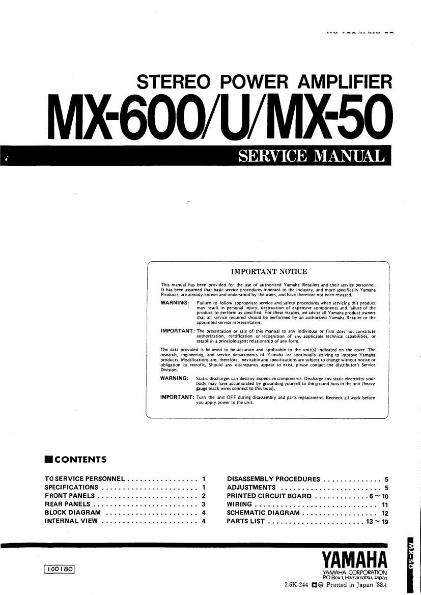
STEREO POWER AMPLIFIER

MX-600/U/MX-50

SERVICE MANUAL

Division.

WARNING:

IMPORTANT NOTICE

This manual has been provided for the use of authorized Yamaha Retailers and their service personnel.
it has been assumed that basic service procedures inherant to the industry, and more specifically Yamaha
Praducu, are already known and understood by the users, and have therefore not been resuled,

WARNING:

Failure rn follow appropriate service and safety prucedures when servicing this product
may result in personal iniury, destruction of expensive components and failure of the
product to perform as specified. For these reasons, we advise an Yamaha product owners
that all service required should be performth by an authorized Yamaha Retailer or the
appornted service representative

IMPORTANT: The presentation or sale of this manual to any individual or firm does not constitute

authorization, certification or recognition of any applicable technical capabilities, or
establish a principle-agent relationship of any form.

The data provided is believed to be accurate and applicable to the uni((s] indicated on the saver. The
research, engineering, and seryice departmenu of Yamaha are continually strivmg to improve Yamaha
products. Modifications are. therefore, inevtrable and specifications are subject to change without notice or
obligation to retrofit. Should any discrepancy appear to exist, please contact the distributors Sewice

Static discharges can destroy expensive components. Discharge any static electricity your
body may have accumulated by grounding yourself to the ground buss in me unit iheayy
gauge black wires connect to this buss).

IMPORTANT: Turn the unit OFF during disassembly and parts replacement. Recheck all work before

you apply power to the unit.

WIRING
SCHEMATICDIAGRAM..................

assumed

DISASSEMBLYPROCEDURES . .
ADJUSTMENTS
PRINTEDCIRCUITBOARD .............6~10

5
5

11
12

PARTSLIST.......................I3~19

YAMAHA

VAMAHA CORPORATION
Boxi Hamamatsu. Japan

2.6K-244 EGP Printed in Japan 88.4

Page 2

MX-600/U/MX-50

I TO SERVICE PERSONNEL

1. Critical Components Information.

Components having special characteristics are marked i
and must be replaced with parts having specifications equal
to those origlnally installed.

2. Leakage Current Measurement (For 120V Model Only).
When service has been completed, it is imperative that you
verify that all exposed conductive surfaces are properly
insulated from supply circuitst

v Meter impedance should be equivalent to 1500 ohm shunted
by 0.15uF.

o Leakage current must not exceed 0.5mA.

0 Be sure to test for leakage with the AC plug in both polarities.

EQUIPMENT AC LEAKAGE TESTER
UNDER TEST on EQUlVALENT
GD :D-- *-
WALL :z -_L-
OUTLET INSULATING TABLE "

I POLARIZATION (U, c models only)
This amplifier product is equipped with a polarized alternat-
ing current line plug la plug having one blade wider than the
other). This plug will fit into the power outlet only one way.
This is a safety feature.

I SPECIFICATIONS
Minimum HMS Output Power par Chennai
20H: ~20kH2
0.003%THD,8S1 I35WIU,C),125WIR,A,B,GI
0.007% THD,6n 160WlU,CI,150W(R,A,B,G)
0.02% THD, 451 190W (U, C, R, A)
Dynamic Power per Channel
Ihy IHF Dynamic Headroom measuring method)
an 220w (U, cl, 175w (R,A,B, G)
en 265W lu,c), 220w (R,A, 3,6)
49 360W (U,C),290W(R,A,B,G)
29 480W (U,C),390W (R,A,B,G)
IQ 500WIU,CI,420W(R,A,B,G)

DIN Standard Output Power per Channel

1kHz,1%THD, 457. 215W (G)
Dynamic Headroom

8n 2.12113

6n 2.19dB

4S1 2.78dB
IEC Power (IItI-Iz, 0.01% THDI

89 140W (GI

sn 170W (GI
Power Band Width

0.03% THO, 67.5w, an lOkHz ~ (30tz
Dumping Factor

80., lkHz 70
Input Sensitivity/Impedance

MAIN IN 1.14V/60kfl
Froquency Ruponu (20H: ~ ZokHII

MAIN IN +0. -0.2dB
Total Harmonic Distortion

20 Hz ~ zokHz

MAIN IN TO SP OUT

(62.5W/8n) 0.003%

Intumodulation Distortion

Rated Output/8&1 0.003%

Signal to Noise Ratio (lHF-A NotworkI
MAIN IN [Shotedi 12305
MAIN IN (5.1 kn terminated) 119dB
Residual Noise (IHEA Network)
16uV
Channel Separation (Vol. -30d3)
Input shorted I1kHz/10kHII 89dB/70dB
Power Supply
A6220/240V, 50H! (B, G)
AC1 1 DIIZU/ZZO/ZMV,
50/60Hz [RI
AC240V, 50H: (AI
Ac120v, 60H: (u, 6)

Power Consumption
650W, BOOVA (U, C)
500W (RI
650W (A, B, G)

AC Outlet
Un Switched x 1

Dimensions (W x H x D)

200W max. (U, C, RI

435 x170 x 425mm
(17-1/8" x 6-11/16" x163/4")

Weight 13kg (28 lbs 11 oz)

'Spscification: are subject to change without notice.

IUI LI.S.A. Model
(C) Canadian Model
(A) Australian Model
(B) British Modal

European Modal
General Mode/

{RI

0 Dimensions

u-ms")

275

FIFIFIFI
l
i
_i
ai
.7;
é
E
a.
n
F l_l LIV-ff
n2!
'5
=2
.1
mm: o o e
:i-- __.__._. E
L_.J L_J _
:II
435 ll7-I/s") S;

Unit 2 mm (insh)