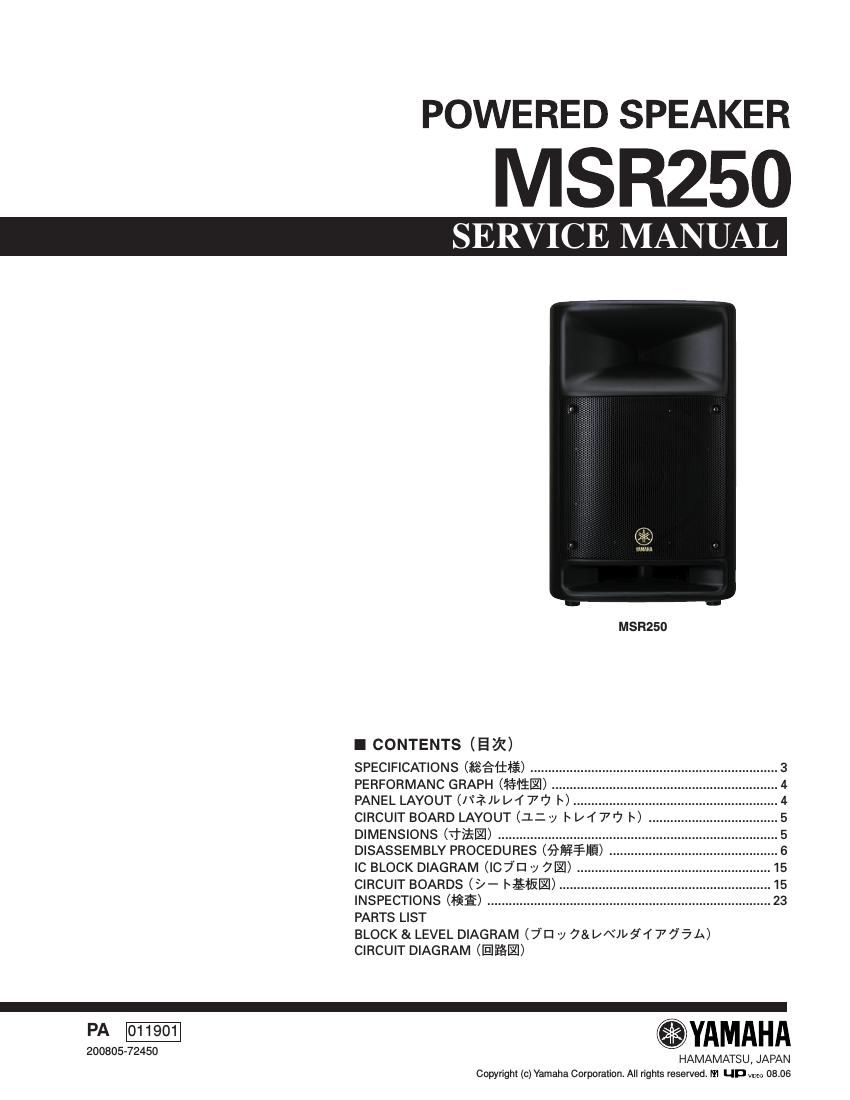
Yamaha msr250 powered speaker service manual

This is the 44 pages manual for yamaha msr250 powered speaker service manual.
Read or download the pdf for free. If you want to contribute, please mail your pdfs to info@audioservicemanuals.com.

Page: 1 / 44
left right
yamaha msr250 powered speaker service manual

Extracted text from yamaha msr250 powered speaker service manual (Ocr-read)


Page 1

MSR250 2  WARNING Components having special characteristics are marked and must be replaced with parts having specification equal to those originally installed. 

Page 2

MSR250 3  SPECIFICATIONSÙ ïù7 General Specifications Type ....................... 2-way Bass Reflex Powered Speaker Speaker Unit LF: ....................................................... 10" (25 cm) Cone HF: ............................. 1" (2.54 cm) Compression Driver Frequency Range ......................... 55 Hz-“20 kHz (-10 dB) Maximum Output Level ................... 116 dB (1 m on Axis) Directional Angle ....................................... 90° (H)/40° (V) Dimension (W x H x D) ................. 342 x 544.5 x 298 mm Weight ................................................................... 14.1 kg Color ......................................................................... Black Tripod Pole Diameter ....................................... 35-“36 mm Included Accessories ..... Power cord (AC inlet type, 2.5 m) Owners Manual Amp. Unit Maximum Output Power ............................... 200 W at 1 kHz, THD=1 %, RL=4 -„¦ Crossover Frequency ......................... 4.0 kHz (LF: 12 dB/oct, HF: 12 dB/oct.) Input Sensitivity INPUT 1 (XLR): ...................... -60 dBu* (MIC), -30 dBu* (LINE) (Phone): ................... -50 dBu* (MIC), -20 dBu* (LINE) INPUT 2/3 (Phone/RCA-pin): .......................................... -20 dBu* Input Impedance INPUT 1: ............................... 2 k-„¦ (XLR), 6 k-„¦ (Phone) INPUT 2/3: ............................................................ 10 k-„¦ Output Impedance ................................ LINK OUT: 600 -„¦ Controls LEVEL Control: .......................................... INPUT 1, 2/3 CH EQ LOW: .......................................±3 dB at 60 Hz HIGH: .....................................±6 dB at 10 kHz POWER Switch (ON/OFF) Input/Output Connectors INPUT 1: ....................... XLR-3-31 / PHONE (balanced) INPUT 2/3: .................. PHONE / RCA-pin (unbalanced) Indicators POWER Indicator: ........................................ Green LED LIMITER Indicator: .......................................... Red LED Power Consumption .................................................. 40 W * 0 dBu=0.775 V Ã- ° `7