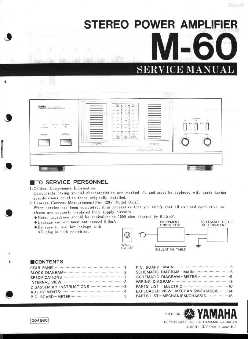
Yamaha m 60

This is the 12 pages manual for yamaha m 60.
Read or download the pdf for free. If you want to contribute, please mail your pdfs to info@audioservicemanuals.com.

Page: 1 / 12
left right
yamaha m 60

Extracted text from yamaha m 60 (Ocr-read)


Page 1

STEREO POWER AMPLIFIER

M-60

ERV E MAN U

l,
o

12:11:: |

l min

.__, [I
O

ITO SERVICE PERSONNEL

l.Critical Components Information.
Components having special characteristics are marked A and must be replaced with parts having
specifieations equal to thnse originally installed.

2.Leakage Current MeasurementlFOr 120V Model Onlyli
When service has been completed, it is imperative that you verify that all exposed conductive su

9 rfaces are properly insulated from supply circuits.
OMeter impedance should be equivalent tu 1500 ohm shunted by 0.15,:4F.
OLeakage current must not exceed 0.5mA. EQUPMENT AC LEAKAGE TESTER
.Be sure to test Inr leakage with UNDER TEST 0 EQUIVALENT
AC plug in both polaritiesi ®
:1 )_- fi
WALL 1:) -I:_
OUTLET INSULATING TABLE
' .CONTENTS
REAR PANEL """"""" P.C, BOARD\MA|N ---------------


SCHEMATIC DIAGRAMMAIN"
SCHEMATIC DIAGRAMMETER --
WIRING DIAGRAM ------
PARTS LIST ELECTRICw
EXPLOADED VIEW ~MECHANISM/CHASSIS
PARTS LIST~MECHANISM/CHASSIS -----------

BLOCK DIAGRAM
SPECIFICATIONS
INTERNAL VIEW-m
DISASSEMBLY INSTRUCTIONS--
. ADJUSTMENTS ---------
\_/ P.C. BOARD ~METER

dustbcbrérb-l

SINCE 1887

004560
NIPPON 613000 CD LTD HAMAMATSU JAPAN

2.6K-7al j; Primed in Japan 34 7

Page 2

M-60

IINTERNAL VIEW

(D Power Transformer
C2) Electrolytic Cap
® Main P.C.B.

(9 Meter P.C.B.

@ Heat Sink

IADJUSTMENTS

Before Adjustments
oWait 2 minutes after power-ON to stabilize amplifier operation.
.Make sure that the main volume is minimum and set Auto-A switch to OFF.

Step Adjustments Location Egaipment Test point Value
Across emitter resistor(0.229l of
. . VR103(L-cht) D.C. V-meter power transistor.
1 'd""9 1mm VR104(R-ch.) Digtal tester R153,R155(L-ch.) 3'0
R154.R156(R-ch,)
2 Auto-A operation Check that the voltage at each test point stated above 0:10 V
confirmation increases when Auto-A switch is turned on. m
(I) Set the load level of the meter at 29 position.
3 "if: 3" mafia-22.)) (2) Adjust VR501 and vnsoz so that OdB of the meter lights
a 5 "9 ' up when the output is f=1KHz and v=34,5v.
Meter CB.
3'" C'B vasouu vnsoztn)
Test PointlL) Test Point (R)


@ vmoa vmoa @

OO


o o