Yamaha jx30 service manual

This is the 10 pages manual for yamaha jx30 service manual.
Read or download the pdf for free. If you want to contribute, please mail your pdfs to info@audioservicemanuals.com.

Page: 1 / 10
left right
yamaha jx30 service manual

Extracted text from yamaha jx30 service manual (Ocr-read)


Page 1

J><®©

SERVICE MANUAL

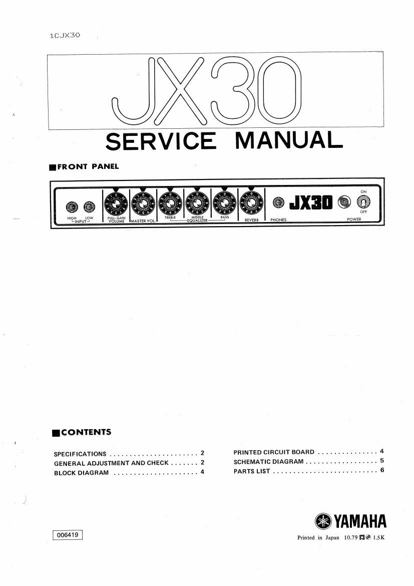
.FRONT PANEL

.IX3II @ @

\
HIGH Iow VULL-GAI TREBLE M DDL

N I E BASS
LINPUTJ VOLUME MASTER VOL. L-v-EQUALIZER- REVERE PHONES POWER
I CONTENTS
SPECIFICATIONS ...................... 2 PRINTED CIRCUIT BOARD ............... 4
GENERAL ADJUSTMENT AND CHECK ....... 2 SCHEMATIC DIAGRAM .................. 5
BLOCK DIAGRAM ..................... 4 PARTS LIST .......................... 6

006419
Printed in Japan 1079 HE? 1.5K

Page 2

JXJO

.SPECIFICATIONS

OUTPUT POWER 30 w (852T.H.D. 3%)

INPUT SENSIVITV PULL-GAIN HIGH -39dB (9mv)
(at 1kHz) push LOW -27dB (ssmvl

PULL-GAIN HIGH -53dB (1.7mVI

MASVOL
EG.VDL
max' pull LOW -41dB(7mV)

VOLUME

INPUT IMPEDANCE HIGH 340KQ, LOW GOKQ

NOISE 755dB (MAS. VVOL"min, VOLUME *min.)
>35dB (MAS. VOL *max, VOLUME amax.)

-25dB (MAS. VOL->max_ VOLUME amax.
PULLG-naulll

REVERB Spring Type

HEADPHONE JACK 78dB (0.3V) @ 30W 89

SPEAKER YAMAHA JA3067 (30 cm) xl

POWER CONSUMPTION Canadian Model 40W 0.5A

Other Models 65W

POWER SOURCE 120V AC fixed, or 110, 130, 220 or

240V AC selectable, 50/60 Hz

DIMENSIONS 473 x 455 x 210 mm
W x H x D 186 x 17.7" x 8.3"
WEIGHT 13.6 kg (30 lbs]

Specifications subject to change without notice.

.GENERAL ADJUSTMENT AND CHECK SPECIFICATIONS

For the measurements, use an oscillator with an output impedance of below 1K9, an oscilloscope and an AC voltmeter/

dB meter with an input impedance of over 100KB.

1. GENERAL ADJUSTMENT
I Idling Current Adjustment
Adjust the pot (B5009) so that the voltage across the
terminals TP1 (+) and TP2 (-) on PM circuit board is
set to 5 t 1mV
*When readjusting all over again (eg. when replacing
the power transistor), make sure to turn the pot full
counterclockwise.

I FIG.I

OPower Supply Voltage Check
Check to ensure that a voltage of Gov is obtained
across TPS (+) and TP6 (-) and 25.5V across TP4 (+)
and TP6 (-).

Idling Current

W
_J
7+?
A)

Power Supply

Power Supply

60V
6 (B