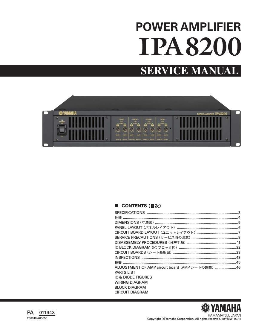
Yamaha ipa8200 power amp service manual

This is the 96 pages manual for yamaha ipa8200 power amp service manual.
Read or download the pdf for free. If you want to contribute, please mail your pdfs to info@audioservicemanuals.com.

Page: 1 / 96
left right
yamaha ipa8200 power amp service manual

Extracted text from yamaha ipa8200 power amp service manual (Ocr-read)


Page 1

POWER AMPLIFIER

IPA8200

I CONTENTS (52X)

SPECIFICATIONS
Iifi ..
DIMENSIONS (TI';
PANEL LAYOUT (/IZJI/ 1/47? I) ..
CIRCUIT BOARD LAYOUT (:L:y I~ [/47'7 I)
SERVICE PRECAUTIONS (U- EZB§®E§) -
DISASSEMBLY PROCEDURES (fi§¥¥III§) ..
IC BLOCK DIAGRAM (IC 7D "J 9.)
CIRCUIT BOARDS (>- IEIIEI) ......
INSPECTIONS ..
fig ....................
ADJUSTMENT OF AMP circuit board (AMP >- IIDEEIE)
PARTS LIST

IC & DIODE FIGURES

WIRING DIAGRAM

BLOCK DIAGRAM

CIRCUIT DIAGRAM

YAMAHA

PA 011943 HAMAMATSU, JAPAN

200910-265650 Copyright Ic)Yamaha Corporation. All rights reserved mIYMW '09.11

Page 2

|PA8200

IMPORTANT NOTICE

This manual has been provided for the use of authorized Yamaha Retailers and their service personnel. It has been assumed that basic service
procedures inherent to the industiy, and more specifically Yamaha Products, are already known and understood by the users, and have there-
fore not been restated.

WARNING: Failure to follow appropriate service and safety procedures when servicing this product may result in personal injury, destruc-
tion of expensive components and failure of the product to perform as specified. For these reasons, we advise all Yamaha
product owners that all service required should be performed by an authorized Yamaha Retailer or the appointed service repre-
sentative.

IMPORTANT: This presentation or sale of this manual to any individual or firm does not constitute authorization, certification, recognition of
any applicable technical capabilities, or establish a principal-agent relationship of any form.

The data provided is believed to be accurate and applicable to the unit(s) indicated on the cover. The research engineering, and service depart-
ments of Yamaha are continually striving to improve Yamaha products. Modifications are, therefore, inevitable and changes in specification are
subject to change without notice or obligation to retrofit. Should any discrepancy appear to exist, please contact the distributors Service Divi-
sion.

WARNING: Static discharges can destroy expensive components. Discharge any static electricity your body may have accumulated by
grounding yourself to the ground bus in the unit (heavy gauge black wires connect to this bus).

IMPORTANT: Turn the unit OFF during disassembly and parts replacement. Recheck all work before you apply power to the unit.

WARNING: This product contains chemicals known to the State of California to cause cancer, or birth defects or other reproductive harm.

DO NOT PLACE SOLDER, ELECTRICAL/ELECTRONIC OR PLASTIC COMPONENTS IN YOUR MOUTH FOR ANY REASON WHAT SO
EVER!

Avoid prolonged, unprotected contact between solder and your skin! When soldering, do not inhale solder fumes or expose eyes to solder/flux
vapor!

If you come in contact with solder or components located inside the enclosure of this product, wash your hands before handling Iood.

IMPORTANT NOTICE FOR THE UNITED KINGDOM
Connecting the Plug and Cord

WARNING: THIS APPARATUS MUST BE EARTHED
IMPORTANT. The wires in this mains lead are coloured in accordance with the following code:

GREEN-AND-YELLOW: EARTH
BLU E: NEUTRAL
BROWN: LIVE

As the colours of the wires in the mains lead of this apparatus may not correspond with the coloured markings identifying the terminals in your
plug, proceed as follows:

The wire which is coloured GREEN and YELLOW must be connected to the terminal in the plug which is marked by the letter E or by the safety
earth symbol (9 or colored GREEN or colored GREEN and YELLOW.

The wire which is coloured BLUE must be connected to the terminal which is marked with the letter N or coloured BLACK.

The wire which is coloured BROWN must be connected to the terminal which is marked with the letter L or coloured RED.

I WARNING (SEE)

Components having special characteristics are marked & and must be replaced with parts having specification equal to those originally
installed.

AEFWEEI; féétfifij'étwliigtififlflffl'. itfifléifiélit fiéOchmlle\f?§Et7)Efllfiaé-ififii<753.