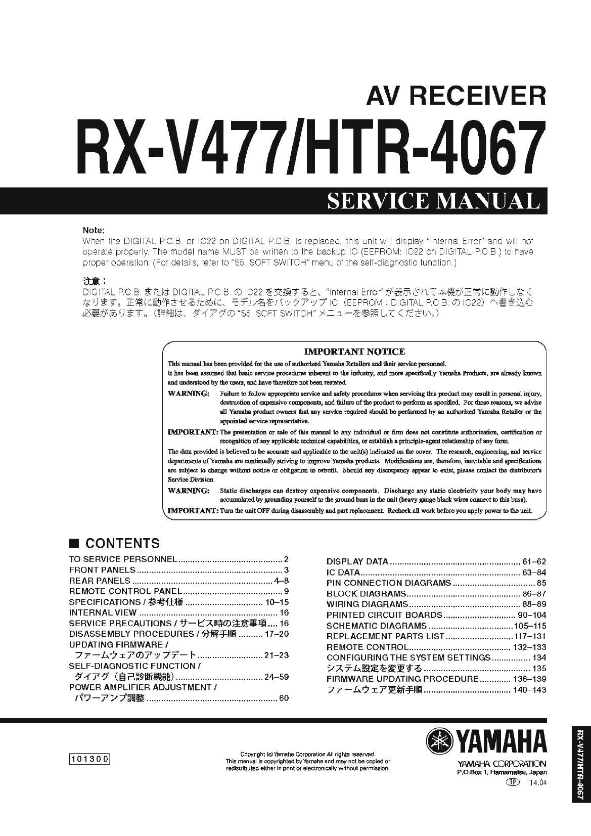
Yamaha htr 4067

This is the 143 pages manual for yamaha htr 4067.
Read or download the pdf for free. If you want to contribute, please mail your pdfs to info@audioservicemanuals.com.

Page: 1 / 143
left right
yamaha htr 4067

Extracted text from yamaha htr 4067 (Ocr-read)


Page 1

AV RECEIVER

RX-V477/HTR-4067

SERVICE MANUAL

Note:

Wheh the DIGITAL PGBT or IG22 Oh DIGITAL PCB Is replaced, this unit will display lhlerhal Error and will hOI
operate properly The model hame MUST be wriiieh to [he backup IO (EEPROM: I022 Oh DIGITAL PCB) 10 have
proper operailohl (For details, refer IO SE. SOFT SWITCH menu oi the sell-diagnostic iunoilon)

31% :

DIGITAL PCB em: DIGITAL PCB. CD IC22 EEETATG b lhierhal ETIOI" bier/nirhmxiennelaenrm <
2320 E32 ERICEUIPECEJTCOIL E?lei%7&1iy77y7° IC (EEPROM : DIGITAL PCB. 03 I022) «germ:
eerie U Ea: (RAMA err???) "85. SOFT SWITCH" #:1-Eéfiifi L? < 731%»)

/ INIPORTANT NOTICE \

This manual has been provided for the use of authorized Yamaha Retailers and their service personnel,

Ithcsheensssmnedthstbanic serviceprocedurca inherenito the industry, andmore specifiesflyYamnhaProdim, arealreadylcnown

nndunderstoodhy thousers, andhavctherefurenothccnremtcd.

WARNING: Failure to follow appropriate service and safety procedures when servicing this product may result in personal injury,
destruction of waive components, and finillne ofthe product In pcrfixm as specifiai. For these reasons, we advise
allYomahnproductow-nm thatnny mviccrcqinrcdshculdhcperfiarmedbyanmuhodzedYemahaRcceflerorthc
appointed service representative.

IMPORTANT: The presentation or sale of this manual to any individual or firm does not constitute authorization, certification or
recognition of any applicable technical capabilities, or establish a pninciple-agent relationship of any form.

The data provided is Inljevedto be accurate and applicable to the units) indicated on the cover. Ihe research, engineering, and service

departments chamahe are continually striving to improve Yamaha products. Modifications are, therefore, inevitable and specifications

are subject to change without notice or obligation no retrofit. Should any discrepancy appear to exist, please coma: the dislrihurors

Service Division

WARNING: Static discharges can destroy expensive components. Discharge any static electricity your body may have
minted by grounding yourself to the ground buss in the unit (heavy gauge black wires connect to this buss).

\MORTANT: Turn the unit OFF during dimmhly and part replacement. Recheck all work before you apply power to the unit. /

I CONTENTS

T0 SERVICE PERSONNEL ------------------------------------------- 2 DISPLAY DATA ...................................................... 61-62
FRONT PANELS --------------------- IC DATA .......................................... .63-34

REAR PANELS ....................... PIN CONNECTION DIAGRAMs ....... 35
REMOTE CONTROL PANEL-m- BLOCK DIAGRAMS ....................... .86-37
SPECIFICATIONSIig-Ifiiifi ..... WIRING DIAGRAMS ..................... 88-89
INTERNAL VIEW ......................................................... 16 PRINTED CIRCUIT BOARDS.. _____ 90_104
SERVICE PRECAUTIONS I fi- BXfifDiifigIE-m 15 SCHEMATIC DIAGRAMS ............. 105-115
DISASSEMBLY PROCEDURES lfiflfllfi ---------- 40 REPLACEMENT PARTS LIST ............................ 117-131
UPDATING FIRMWARE/ _., REMOTE CONTROL .......................................... 132-133

77-57177037'7 7T- l ........................... 21-23 CONFIGURINGTHE SYSTEM SETTINGS ________________ 134
SELF-DIAGNOSTIC FUNCTION / :71 7'AEQEEEEE3'6 ............................................ 135

51477 (E Eififlfifiéé) .................................... 24-59 FIRMWARE UPDATING PROCEDURE ............. 136-139
POWER AMPLIFIER ADJUSTMENT] 77-A617Efifllfi .................................... 140-143

xiv-777mg ...................................................... 60

.YAMAHA

1 0 1 3 0 0 Copyright lclYamaha Corporation All rights reserved.
This manual is copyrighted tor/Yamaha and may not be copied or D h n 9| In RPORP D"
redistributed either in print or electronically without permission. Y (D T
P.O.Bon< 1. Hamamatsu. Japan

14.04

II
5
E
.4
d
:l:
-
.3
h
c:
m
N

Page 2

S
o
I
it:
'-
E
h-
E
>.
><
fl:

RX-V477/HTR4067

I TO SERVICE PERSONNEL

1. Critical Components information

Components haying speCial characteristics are marked 11: and
must be replaced with parts having specifications equal to
those originally installed:

2. Leakage Current Measurement (For 120V Models Only)

When service has been completed, it is imperative to verity
that all exposed conductive surfaces are properly insulated
from supply circuits:

- Meter impedance should be equivalent to i500 ohms shunted
by O.l5 pl:

For U model
an CAUTION

AC LEAKAGE
WALL EQUlPMENT TESTER OR
OUTLET UNDER TEST EQUIVALENT

(DID-

J.-

lNSULATlNG
TABLE

- Leakage current must not exceed 0.6mA:
- Be sure to test tor leakage with the AC plug in both polarities:

-A-V "F5401: FOR CONTiNUED PROTECTlON AGAINST RISK OF FiRE, REPLACE ONLY WiTH SAME TYPE 2A,

250V FUSE

F5402: FOR CONTlNUED PROTECTlON AGAINST RISK OF FlRE, REPLACE ONLY WlTH SAME TYPE 6A,

125V FUSE

For C model
CAUTION

F540i: REPLACE WITH SAME TYPE 2A, 250V FUSE
F5402: REPLACE WITH SAME TYPE 6A, i25V FUSE

ATTENTION

F540i: UTiLlSER UN FUSIBLE DE RECHANGE DE MEME TYPE DE 2A, 250V.
F5402: UTiLlSER UN FUSIBLE DE RECHANGE DE MEME TYPE DE 6A, i25V.

WARNING: CHEMICAL CONTENT NOTICE!

This product contains chemicals KROWR IO the State Oi California [0 cause cancer, or birth CIQIBCIS Ol OIITGT reproductive

harm.

DO NOT PLACE SOLDER, ELECTRlCAL/ELECTRONIC OR PLASTIC COMPONENTS lN YOUR MOUTH FOR ANY REASON

WHATSOEVER!

AVOid prolonged, unprotected contact between solder and your SKifll When soldering, do not inhale solder iumes or

expose eyes to solder/flux vapor!

il you come in contact with solder or components located inside the enclosure oi this product, wash your hands beiore

handling food.

About lead free solder/fififilV/fiIE'DLT

All ol the P088 installed in this unit and solder leints are
soldered using the lead tree solder

Among some types cl lead tree solder currently available,
it is recommended to use one ct the tollowing types lor
the repair work

- Sn 4- Ag + Cu (tin + silver + copper)

- Sn + Cu (tin + copper)

- Sn + Zn + Bi (tin + zinc + bismuth)

Caution:

As the melting iodinl temperature of the lead tree solder is
about 30° 0 to 40° C (50° F to 70° F) higher than that oi
the lead solder, be sure to use a soldering iron suitable to
each solder.

asueaanroesatceeasdnyaaem
seaeeeeenyaenysdeehtoatt
fififly§hmb<flfiwfififi@UE?fi\@fi%h
d?fi®$5#fi%fl>@®@fi%flfibsso

- Sn+Ag+Cu ($53 + Ea + W)

- Sn+Cu (fig +filfi)

- Sn+Zn+Bi as + see + 51770
as:
easy \yecsiaais seasons/ex U /\//§°l:l:l:{ 30 ~
mrfige EAV§ET%Efifi<fiéDD