Yamaha g30 112 series i a service manual

This is the 11 pages manual for yamaha g30 112 series i a service manual.
Read or download the pdf for free. If you want to contribute, please mail your pdfs to info@audioservicemanuals.com.

Page: 1 / 11
left right
yamaha g30 112 series i a service manual

Extracted text from yamaha g30 112 series i a service manual (Ocr-read)


Page 1

* «use.

630-112 (s/# 4801~l

ISPECIFICATIONS

Output Power 30 Watts RMS @ 3% THD 8 ohms
40 Watts RMS @ 10% THD 8 ohms
Speaker 30 cm (12") x 1 JA3059
Input Sensitivity HIGH : -34 dBm @ 1KHZ (Volume & Tone Controls at max.)
LOW :-28 dBm
Input Impedance HIGH : 1M ohms
LOW : 130K ohms
Head Phone Terminal -7 dBm @ 1KHZ/8 to 150 ohms head phone
Controls Volume
Bass, Treble, Bright
Distortion
Reverb
Foot Switch Jack Distortion
Reverb
Semi-Conductor in use Transistors 14
FET 2
Diodes 9
Rated Voltage AC 100V
Rated Frequency 50/60 Hz
Rated Power Consumption 30 Watts
Dimensions 450 (H) x 500 (W) x 200 (D) m/m
Weight 12.6 kg
Finish Black leatherette

Specifications subject to change without notice.

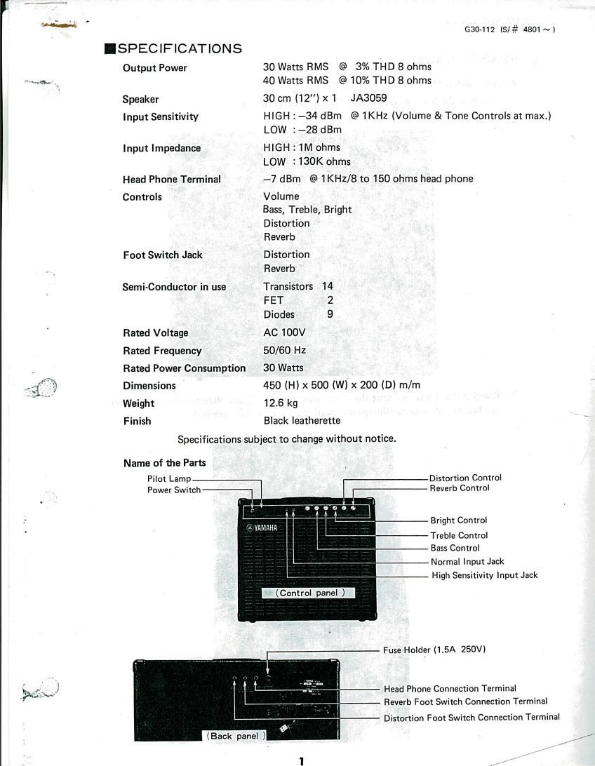
Name of the Parts

Pilot Lamp
Power Switch

Distortion Control
Reverb Control

Bright Control

Treble Control
Bass Control

3 YAMAHA

Normal Input Jack
High Sensitivity Input Jack

Fuse Holder (1.5A 250V)

Head Phone Connection Terminal
Reverb Foot Switch Connection Terminal

Distortion Foot Switch Connection Terminal

Page 2

T- a-

630112 (S/# 4801~) 2.

IDISASSEMBLY

\>-'

Amp. Unit Removal (Used the Figure in this section)

A. Remove the 6 screws (marked 0) and remove the back cover.

B. Remove the 4 screws fixing the Amp. unit (See Fig. 2) and slide out the unit. Before slide
out the unit, disconnect the speaker cord from the speaker terminal.

Fig 2