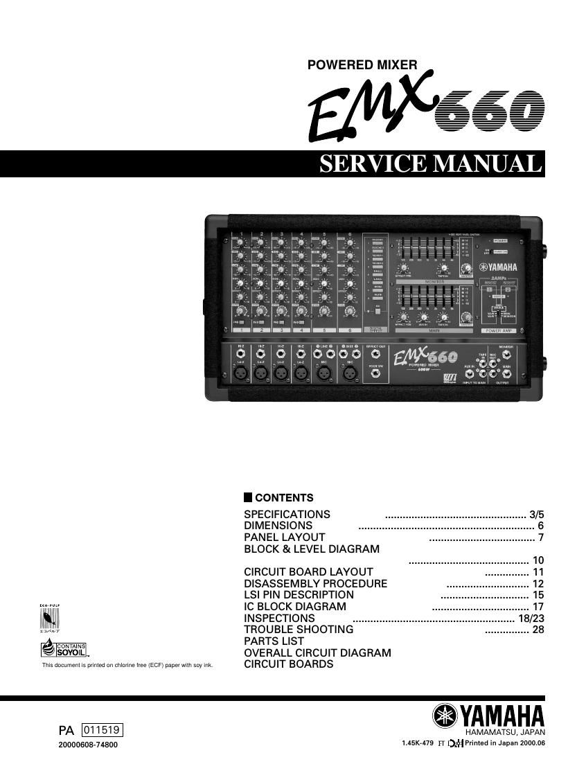
Yamaha emx 660

This is the 52 pages manual for yamaha emx 660.
Read or download the pdf for free. If you want to contribute, please mail your pdfs to info@audioservicemanuals.com.

Page: 1 / 52
left right
yamaha emx 660

Extracted text from yamaha emx 660 (Ocr-read)


Page 1

EMX660 2 2 IMPOR TANT NOTICE This manual has been provided for the use of authorized Yamaha Retailers and their service personnel. It has been assumed that basic service procedures inherent to the industry, and more specifically Yamaha Products, are already known and under- stood by the users, and have therefore not been restated. WARNING : Failure to follow appropriate service and safety procedures when servicing this product may result in per- sonal injury, destruction of expensive components and failure of the product to perform as specified. For these reasons, we advise all Yamaha product owners that all service required should be performed by an authorized Yamaha Retailer or the appointed service representative. IMPORTANT : This presentation or sale of this manual to any individual or firm does not constitute authorization certifi- cation, recognition of any applicable technical capabilities, or establish a principal-agent relationship of any form. The data provided is belived to be accurate and applicable to the unit(s) indicated on the cover. The research engineering, and service departments of Yamaha are continually striving to improve Yamaha products. Modifications are, therefore, inevitable and changes in specification are subject to change without notice or obligation to retrofit. Should any discrepancy appear to exist, please contact the distributorÕs Service Division. WARNING : Static discharges can destroy expensive components. Discharge any static electricity your body may have accumulated by grounding yourself to the ground bus in the unit (heavy gauge black wires connect to this bus.) IMPORTANT : Turn the unit OFF during disassembly and parts replacement. Recheck all work before you apply power to the unit. WARNING: CHEMICAL CONTENT NOTICE! The solder used in the production of this product contains LEAD. In addition, other electrical/electronic and/or plastic (Where applicable) components may also contain traces of chemicals found by the California Health and Welfare Agency (and possibly other entities) to cause cancer and/or birth defects or other reproductive harm. DO NOT PLACE SOLDER, ELECTRICAL/ELECTRONIC OR PLASTIC COMPONENTS IN YOUR MOUTH FOR ANY REASON WHAT SO EVER! Avoid prolonged, unprotected contact between solder and your skin! When soldering, do not inhale solder fumes or expose eyes to solder/flux vapor! If you come in contact with solder or components located inside the enclosure of this product, wash your hands before handling food. WARNING Components having special characteristics are marked and must be replaced with parts having specification equal to those originally installed. 2

Page 2

3 EMX660 SPECIFICATIONS General specifications - 0 dB=0.775 Vrms Maximum output power300 W + 300 W/4ohms @0.5% THD at 1 kHz (POWER AMP OUT 1, 2) 215 W + 215 W/8ohms @0.5% THD at 1 kHz (POWER AMP OUT 1, 2) 600 W/8ohms @0.5% THD at 1 kHz (BRIDGE) Frequency response20 Hz~20 kHz +1 dB, -3 dB @1 W output into 8ohms (POWER AMP OUT) 20 Hz~20 kHz +1 dB, -3 dB @+4 dB output into 10 kohms (MAIN OUT, MONITOR OUT, EFFECT SEND) Total harmonic distortionLess than 0.5% @20 Hz~20 kHz, 150 W output into 4ohms (POWER AMP OUT 1, 2) Less than 0.3% @20 Hz~20 kHz, +14 dB output into 10 kohms (MAIN OUT, MONITOR OUT, EFFECT OUT) Hum & noise (Average, Rs=150W) (with 20 Hz~20 kHz BPF)-124 dB equivalent input noise, -65 dB residual output noise (POWER AMP OUT) -88 dB residual output noise (MAIN OUT, MONITOR OUT, EFFECT SEND) -79 dB (83 dB S/N) MAIN OUT, MONITOR OUTMaster level control at nominal level and all channel level controls at minimum. -69 dB (73 dB S/N) MAIN OUT, MONITOR OUTMaster level control at nominal level and 1 channel level control at nominal level. -75 dB (79 dB S/N) EFFECT SENDMaster level control at nominal level and all channel level controls at minimum. -69 dB (73 dB S/N) EFFECT SENDMaster level control at nominal level and 1 channel level control at nominal level. Maximum voltage gain (PAD: OFF)88 dB CH IN (Lo-Z) to POWER AMP OUT (CH1~4) 66 dB CH IN (Lo-Z) to MAIN OUT, MONITOR OUT (CH1~4) 72 dB CH IN (Lo-Z) to EFFECT OUT (CH1~4) 48 dB CH IN (Lo-Z) to REC OUT (CH1~4) 56 dB CH IN (Hi-Z) to MAIN OUT, MONITOR OUT (CH1~4) 26 dB AUX IN to MAIN OUT 24 dB TAPE IN to MAIN OUT 66 dB MIC IN to MAIN OUT, MONITOR OUT (CH5-6) 26 dB LINE IN to MAIN OUT, MONITOR OUT (CH5) 46 dB INST IN to MAIN OUT, MONITOR OUT (CH6) Crosstalk at 1 kHz65 dB adjacent input, 65 dB input to output Input channel equalization±15 dB Maximum HIGH 12 kHz shelving* MID 2.5 kHz peaking LOW 80 Hz shelving* * Turn over/roll-off frequency of shelving: 3 dB below maximum variable level. Meters5 POINTS LED METER (-10, -5, 0, +3, +6 dB) (MAIN OUT, MONITOR OUT) Graphic equalizer7 bands (125, 250, 500, 1 k, 2 k, 4 k, 8 kHz), ±12 dB Maximum (MAIN OUT, MONITOR OUT) Internal digital effect8 types (VO.ECHO 1, VO.ECHO 2, VO.REV. 1, VO.REV. 2, HALL 1, HALL 2, ROOM, PLATE) Phantom power+15 V is supplied to electrically balanced inputs for powering condenser microphones via 2.4 kohms current limiting/isolation resisters. LimiterComp. : THD³0.5% (POWER AMP OUT) LIMIT indicatorsTurns on. : THD³0.5% (POWER AMP OUT) Protection Circuit (Power Amp.)POWER Switch on/off Mute, DC Detection, Temp (Heatsink Temp³90˚C) Foot switch (FC-5)DIGITAL EFFECT MUTE : on/off Power requirementUSA and Canada 120 V AC 60 Hz Europe 230 V AC 50 Hz Other 240 V AC 50 Hz Power consumption250 W Dimensions (WxHxD)497´275´275 mm Weight17 kg