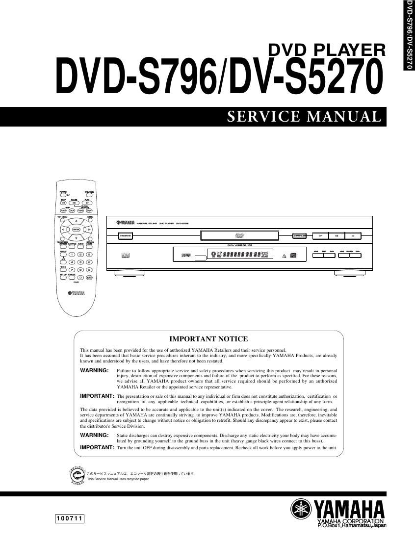
Yamaha dvd s796

This is the 82 pages manual for yamaha dvd s796.
Read or download the pdf for free. If you want to contribute, please mail your pdfs to info@audioservicemanuals.com.

Page: 1 / 82
left right
yamaha dvd s796

Extracted text from yamaha dvd s796 (Ocr-read)


Page 1

DVD PLAYER

DVD-S796/DV-S5270

SERVICE MANUAL

QWWAA Mmmlnua memes m1...

are; big |:| ismamsamufl g. @ I:I:I :IZI

MPORTANT NOTICE

This manual has been provided for the use of authorized YAMAHA Retailers and their service personnel
it has been assumed that basic servrce procedures inherant to the industry. and tnore specifically YAMAHA Products. are already
known and understood by the users. and have therefore not been restated

WARNING: Failure to follow appropriate service and safety procedures when servicing this product may result in personal
illjuly. destruction of expensive components and failure of the product to perform as specified. For these reasons.
we advise all YAMAHA product owners that all service required should he performed by art authorized
YAMAHA Retailer or the appointed service representative

IMPORTANT: The presentation or sale of this manual to any indivtdual or firm does ROI constitute authorization. centficauon oi-
recognilion of any applicable technical capabilities. or establish a principleeagent relationship of any form

The data provided is believed to be accurate and applicable to the unit(s> indicated on the cover, The research. engineering and
service departments of YAMAHA are continually striving to improve YAMAHA product ~. Modifications are, therefore. inevitable
and specifications are subject to change without notice or obligation to retrofit. Should any discrepancy appear to exist. please contact
the distributors Service Division.

WARNING: Static discharges can destroy expensive components. Discharge any static electricity your body may have acciimue
lated by grounding yourself to the ground buss in the unit (heavy gauge black wires connect to this buss).

. IMPORTANT: Turn the unit OFF during disassembly and parts replacement. Recheck all work before you apply power to the unit. I.

./

(I 109*b17:17lut. 137*7iiiwiimififi L/(UiT
This Sevvlce Manual uses vecycled papev

ea or
we;

.YAMAHA

WEORPO AT ON
amama

0
<
.0
U)
1
Lo
3
0
.<
U)
u:
M
1
o

Page 2

D
h
N
In
R
>
9
0
m
n
W
D
>
D

CONTENTS

SPECIFICATIONS ................................................................ 1-1
LOCALE MANAGEMENT INFORMATION .
TO SERVICE PERSONNEL ....................
PREVENTION OF ESD TO ES DEVICES.
PRECAUTION OF LASER DIODE..........
HANDILNG PRECAUTIONS FOR TRAVERSE DECK.
REAR PANELS .......................................................... .
OPTICAL PICKUP SELF- DIAGNOSIS AND REPLACEMENT PROCEDURE. 1-6
SELF-DIAGNOSIS FUNCTION AND SERVICE MODES...
SERVICE PRECAUTIONS .................
SERVICE TOOLS AND EQUIPMENT.
OPERATING INSTRUCTIONS .......................................... 1- 10

SECTION 2

ASSEMBLING AND DISASSEMBLING THE CASING AND CHECKING
C. B. A.s
1.Disassembly Procedure .....
2.Casing Parts and C.B.A. PosI Ions 2-2
3.8ervice Positions...
4.Disassembling the Top Cove
5.Disassembling the Tray
6.Disassembling the From Panel ......
7.Disassembling the Loading Base Uni
8.Checking the Module C.B.A.
9.Disassembling the Rear Panel
10.Checking the Power Supply C.B.A.
11.Checking the Mother C.B.A
12 Checking the Power Switch C.B.A. ..
13.Checking the Front Switch C.B.A.

ASSEMBLING AND DISASSEMBLING THE OPTICAL PICKUP

1.Handling the Optical Pickup .. 2-6
2.Disassembly Procedure
3.Lubricating the Loading Base Unit
4. Static Electricity Countermeasures ..
5. Disassembling the Clamp Base Unit.. .....2-9
6. Disassembling the Clamper Weight CIamper Yoke

Magnet and Clamper ............
7.Disassembling the Traverse Unit
8.Disassembling the Stepping Motor Uni
9.Disassembling the Optical Pickup Unit
10.Disassembling the Nut Unit .........................
11.Disassembling the Sub»Shaft Preload Spring
12.Assembling the Optical Pickup ......................
13.Disassembling the Spindle Motor Unit.
14.0ptical Pickup Tilt Adjustment
15.Disassembling the Intermediate Chassis ..........
16.Disassembling the Vertical Cam and Drive Gear
17.Disassembling the Pulley Gear and Deceleration Gear 2-15
18.Disassembling the Mechanism Loading C.B.A.
19.Lubricating the Optical Pickup and Peripheral parts .....2-16


ELECTRICAL CONFIRMATION
1.Video Output (Luminance Signal) Confirmation ........ 2-17
2.Video Output (Chrominance Signal) Confirmation ....2-17
3.Video Component Signal (CB) Output Confirmation .2-18

SECTION 3

ABBREVIATIONS ................................................................. 3-1

BLOCK DIAGRAM
1.0VERALL BLOCK DIAGRAM . 3-3
2.SERVO BLOCK DIAGRAM .. 3-4
3.VIDEO BLOCK DIAGRAM (FOR U, A, R MODELS) .3-5
4.V|DEO BLOCK DIAGRAM (FOR G, B MODEL) ......... 3-6
5.AUDIO BLOCK DIAGRAM ............................................ 3-7

INTERCONNECTION DIAGRAM
1.U, A, R MODELS ........................................................... 3-8
2.G, B MODELSs-Q

SCHEMATIC DIAGRAM
1.POWER SUPPLY SCHEMATIC DIAGRAM (FOR U MODEL) ...... 3-10
2.POWER SUPPLY SCHEMATIC DIAGRAM (FOR G, B, A MODELS) . 3-11
3.POWER SUPPLY SCHEMATIC DIAGRAM (FOR R MODEL 3-12
4.ADSC (MODULE C.B.A. 1/6) SCHEMATIC DIAGRAM ..... 3-13
5.AV DECODER [MODULE C.B.A. 2/6)
SCHEMATIC DIAGRAM (FOR U MODEL) .....
6.AV DECODER (MODULE C.B.A 2/6)
SCHEMATIC DIAGRAM (FOR G, B, A, R MODELS) .......... 3-15
7.AUD|O (MODULE C.B.A. 3/6) SCHEMATIC DIAGRAM 3-16
8.FEF' (MODULE C.B.A. 4/6) SCHEMATIC DIAGRAM....3-17
9.CPU (MODULE C.B.A. 5/6) SCHEMATIC DIAGRAM ........ 3-18
10.0DC (MODULE C.B.A. 6/6) SCHEMATIC DIAGRAM...3-19
11.VIDEO OUT (MOTHER C.B.A. 1/4)

SCHEMATIC DIAGRAM (FOR U, A, R MODELS) ...3-20
12.V|DEO OUT (MOTHER C.B.A 1/4)

SCHEMATIC DIAGRAM (FOR G, B MODELS) ........ 3-21
13.AUDIO OUT1 (MOTHER C.B.A. 2/4) SCHEMATIC DIAGRAM 3-22
14.AUDIO OUT2 (MOTHER C.B.A. 3/4) SCHEMATIC DIAGRAM. 3-23
15.0PERATION (MOTHER C.B.A. 4/4) SCHEMATIC DIAGRAM ...... 3-24
16.FRONT SW AND POWER SW SCHEMATIC DIAGRAM .. 3-25
17.SCART SCHEMATIC DIAGRAM (FOR G, B MODELS) 3-26

3-14

CIRCUIT BOARD DIAGRAM

1.POWER SUPPLY C.B.A. (FOR U MODEL). 3-27

2.POWER SUPPLY C.B.A. (FOR G, B, A MODELS) 3-28
3.POWER SUPPLY C.B.A. (FOR R MODEL). .3-29
4. MODULE C. B. A.. .3-30

5. MOTHER C. B. A. .3-32
6. FRONT SW AND POVIIER SIIV C. B. A. 3-33
7.SCART C.B.A. (FOR G, B MODELS) ........................ 3-34

SECTION 4

EXPLODED VIEWS & REPLACEMENT PARTS LIST
1.Electrical Replacement Parts List ............................... 4-11
2.Casing Parts & Mechanism Section. .4-13
3.Loading Mechanism Section .4-15
4.Traverse Section ............ .4-17
5.Remote Control Transmitter. .4-18