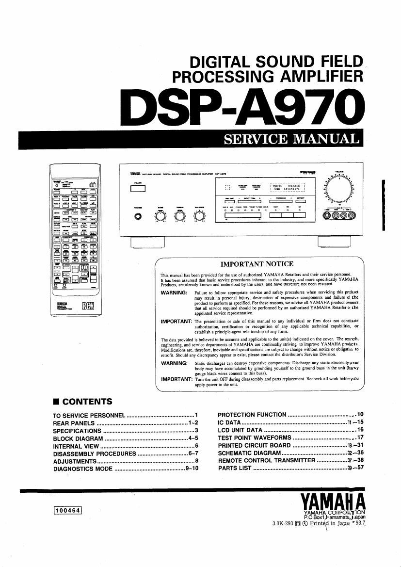
Yamaha dsp a970

This is the 77 pages manual for yamaha dsp a970.
Read or download the pdf for free. If you want to contribute, please mail your pdfs to info@audioservicemanuals.com.

Page: 1 / 77
left right
yamaha dsp a970

Extracted text from yamaha dsp a970 (Ocr-read)


Page 1

DIGITAL SOUND FIELD
PROCESSING AMPLIFIER

SP-A97O

SERVICE MANUAL

AU

liflVIE mire"
1m. mint-re

nonnueouun

[LEM

ED
3;

WARNING:

IMPORTANT:

WARNING:

IMPORTANT:

I CONTENTS

TO SERVICE PERSONNEL
REAR PANELS
SPECIFICATIONS ..
BLOCK DIAGRAM .
INTERNAL VIEW ....................
DISASSEMBLI PROCEDURES
ADJUSTMENTS .........
DIAGNOSTICS MODE .

ms rnpnuul has been provided for the use of uuihorized YAMAHA Reuilen and LIIcir service personnel.
It has been assumed thnt basic service pmcedurcs inherent to the industry, unit more specifically YAMAHA
Products. at: allEde known and underfloor! by me uscrs. 8nd hive therefore not bean mslamd.

The data provided is believed to be accurate tmd applicabie lo the unil(s) indicated on the cover. The march,
engineering, and service depanments of YAMAHA are continually striving to improve: YAMAHA predicts.
Modifications are.
retrofit. Should any discrepancy appear to exisl, please contact the distributors Service Division.


IMPORTANT NOTICE

Failure to follow apprapriale suvice and safely proccdurer when servicing this product
may result in personal injury. destruction of expensive components and failure a? me
product to perform as specified. For ihcse reasons. we advise ull YAMAHA product omen
that III scrviw required nhouId be performed by an aulhorimd YAMAHA Retailer or the
appoinzed service rcprcsentalive.

The prescnmiian or sale of this manual to any individual or firm does not conmlute
authorization. certification or recognition of any applicablc technical capabilitiet, or
establish a principle-agent relationship of any form.

therefore, inevitable and specifications are sublect to change without notice or obligalim to

Static discharges can destroy expensive components. Discharge any static electricilyyour
body may have accumulated by grounding yourself to the ground buss in the unit (navy
guuge Mack wimlt com»! to this buss).

Turn the unit OFF during disassembly and pans replacement. Recneclr all work bci'anyou
apply power to the unit.

PROTECTION FUNCTION .........
IC DATA ..........
LCD UNIT DATA ..
TEST POINT WAVEFORMS
PRINTED CIRCUIT BOARD
SCHEMATIC DIAGRAM"
REMOTE CONTROL TRANSMITTER
PARTS LIST ...........

YA

YAMAHA CORPORATION
P.0.Box1,Hamamaiqu 3P6!

3t0K~293 [fl 6) Printd in Japal 93].
X

Page 2

DSP-A970

I TO SERVICE PERSONNEL

1. Critical Components Information. ' AC LEAKAGE
Components having special characteristics are marked and WALL EQUIPMENT TESTER OH
must be replaced with parts having specifications equal to OUTLET UNDER TEST EQUIVALENT

those originally installed.

2. Leakage Current Measurement (For 120V Models Only). ® D
When service has been completed, it is imperative lo verily
that all exposed conductive surleces are properly insulated =

from supply circuits INSULATING
TABLE

0 Meter impedance should be equivalent lo 1500 ohm shunted
by 01 SpF.

o Leakage current must not exceed oSmAt

0 Be sure to test Ior leakage with the AC plug in both
polarities

WARNING: CHEMICAL CONTENT NOTICE!

The solder used in the production of this product contains LEAD. In addition, other electrical/electronic
and/or plastic (where applicable) components may also contain traces ol chemicals found by the
California Health and Welfare Agency (and possibly other entities) to cause cancer and/or birth defects
or other reproductive harm.

DO NOT PLACE SOLDER, ELECTRICAL/ELECTRONIC OR PLASTIC COMPONENTS IN YOUR MOUTH
FOR ANY REASON WHATSOEVER!

Avoid prolonged, unprotected contact between solder and your skin! When soldering, do not inhale
solder fumes or expose eyes to solder/flux vapor!

If you come in contact with solder or components located inside the enclosure of this product, wash your
hands before handling food.

I REAR PANELS

V USA & Canadian models