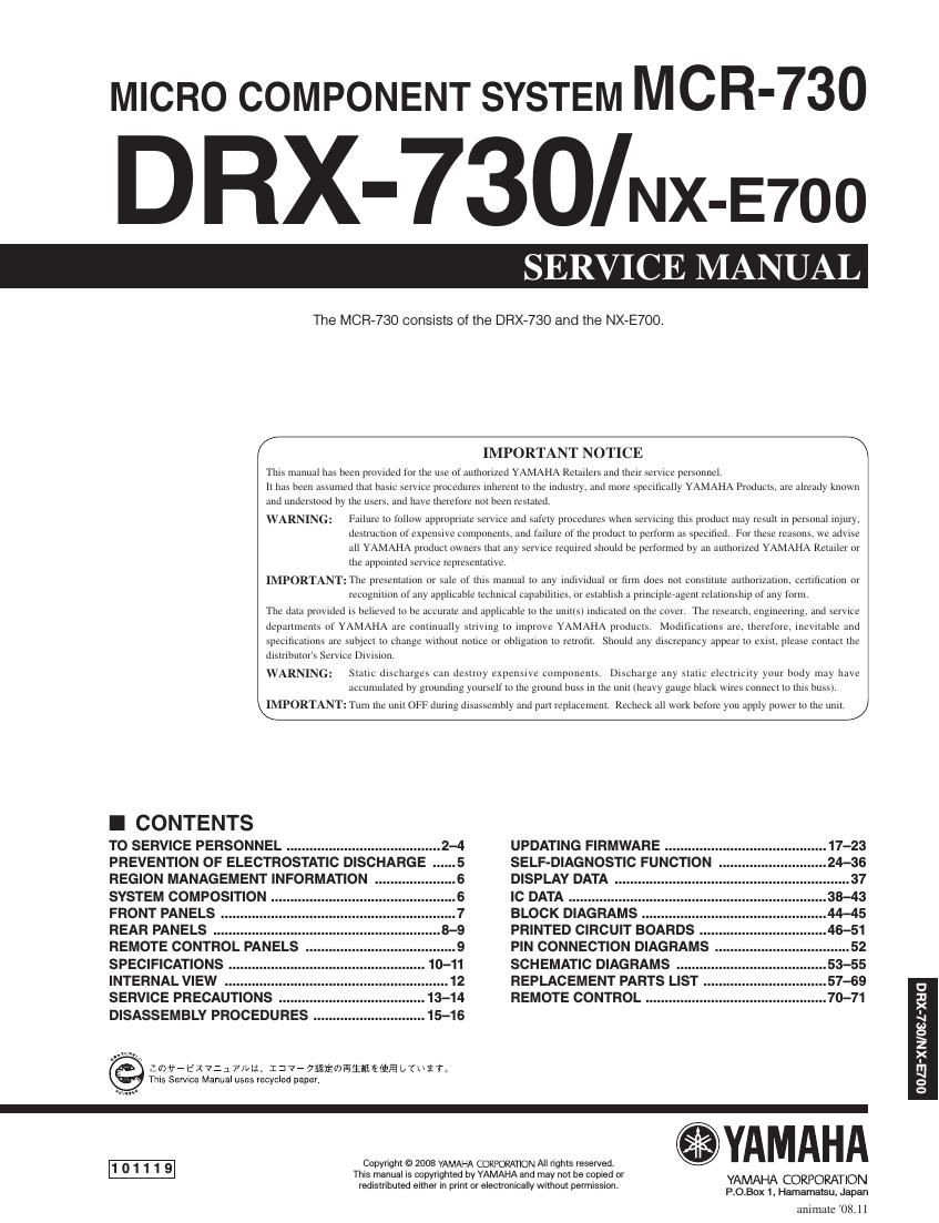
Yamaha drx 730

This is the 71 pages manual for yamaha drx 730.
Read or download the pdf for free. If you want to contribute, please mail your pdfs to info@audioservicemanuals.com.

Page: 1 / 71
left right
yamaha drx 730

Extracted text from yamaha drx 730 (Ocr-read)


Page 1

2 DRX-730/NX-E700 DRX-730/NX-E700 This product contains chemicals known to the State of California to cause cancer, or birth defects or other reproductive harm. DO NOT PLACE SOLDER, ELECTRICAL/ELECTRONIC OR PLASTIC COMPONENTS IN YOUR\ MOUTH FOR ANY REASON WHATSOEVER! Avoid prolonged, unprotected contact between solder and your skin! When soldering, do not inhale solder fumes or expose eyes to solder/flux vapor! If you come in contact with solder or components located inside the encl\ osure of this product, wash your hands before handling food. 1. Critical Components InformationComponents having special characteristics are marked /  and must be replaced with parts having specifications equal to those originally installed. 2. Leakage Current Measurement (For 120V Models Only) When service has been completed, it is imperative to verify that all exposed conductive surfaces are properly insulated from supply circuits. - Meter impedance should be equivalent to 1500 ohms shunted by 0.15 μF. CAUTION F501: FOR CONTINUED PROTECTION AGAINST RISK OF FIRE, REPLACE ONLY WITH SAME TYPE 4A, 125V FUSE. CAUTION F501: REPLACE WITH SAME TYPE 4A, 125V FUSE. ATTENTION F501: UTILISER UN FUSIBLE DE RECHANGE DE MÉME TYPE DE 4A, 125V. All of the P.C.B.s installed in this unit and solder joints are soldered using the lead free solder. Among some types of lead free solder currently available, it is recommended to use one of the following types for the repair work. - Sn + Ag + Cu (tin + silver + copper) - Sn + Cu (tin + copper) - Sn + Zn + Bi (tin + zinc + bismuth) Caution: As the melting point temperature of the lead free solder is about 30°C to 40°C (50°F to 70°F) higher than\ that of the lead solder, be sure to use a soldering iron suitable to each solder. -–  TO SERVICE PERSONNEL - Leakage current must not exceed 0.5mA. - Be sure to test for leakage with the AC plug in both polari- ties. WALL OUTLET EQUIPMENT UNDER TEST AC LEAKAGE TESTER OR EQUIVALENT INSULATING TABLE WARNING: CHEMICAL CONTENT NOTICE! About lead free solder

Page 2

3 DRX-730/NX-E700 DRX-730/NX-E700 WARNING: Laser Safety This product contains a laser beam component. This component may emit invisible\ , as well as visible radiation, which may cause eye damage. To protect your eyes and skin from laser radiation, the following precautions must be used during servicing of the unit. 1) When testing and/or repairing any component within the product, keep your eyes and skin more than 30 cm/1 feet away from the laser pick-up unit at all times. Do not stare at the laser beam at any time. 2) Do not attempt to readjust, disassemble or repair the laser pick-up, unless noted elsewhere in this manual. 3) CAUTION: Use of controls, adjustments or performance of procedures other than those specified herein may result in hazardous radiation exposure. Laser Emitting conditions: 1) When the Top Cover is removed, and the STANDBY/ON SW is turned to the ON position, the laser component will emit a beam for several seconds to detect if a disc is present. During this time (5-10 sec.) the laser may radiate through the lens of the laser pick-up unit. Do not attempt any servicing du\ ring this period! If no disc is detected, the laser will stop emitting the beam. When a di\ sc is loaded, you will not be exposed to any laser emissions. 2) The laser power level can be adjusted with the VR on the pick-up PWB, ho\ wever, this level has been set by the factory prior to shipping from the factory. Do not adjust this laser level control unless instruction is provided elsewhere in this manual. Adjustment of this control can increase the laser emission level from the device. Type: Semiconductor laser AlGaInP Wave length: 655 nm (DVD) 790 nm (VCD/CD) Output Power: 5 mW (DVD) 7 mW (VCD/CD) Beam divergence: 20 degree Laser Diode Properties