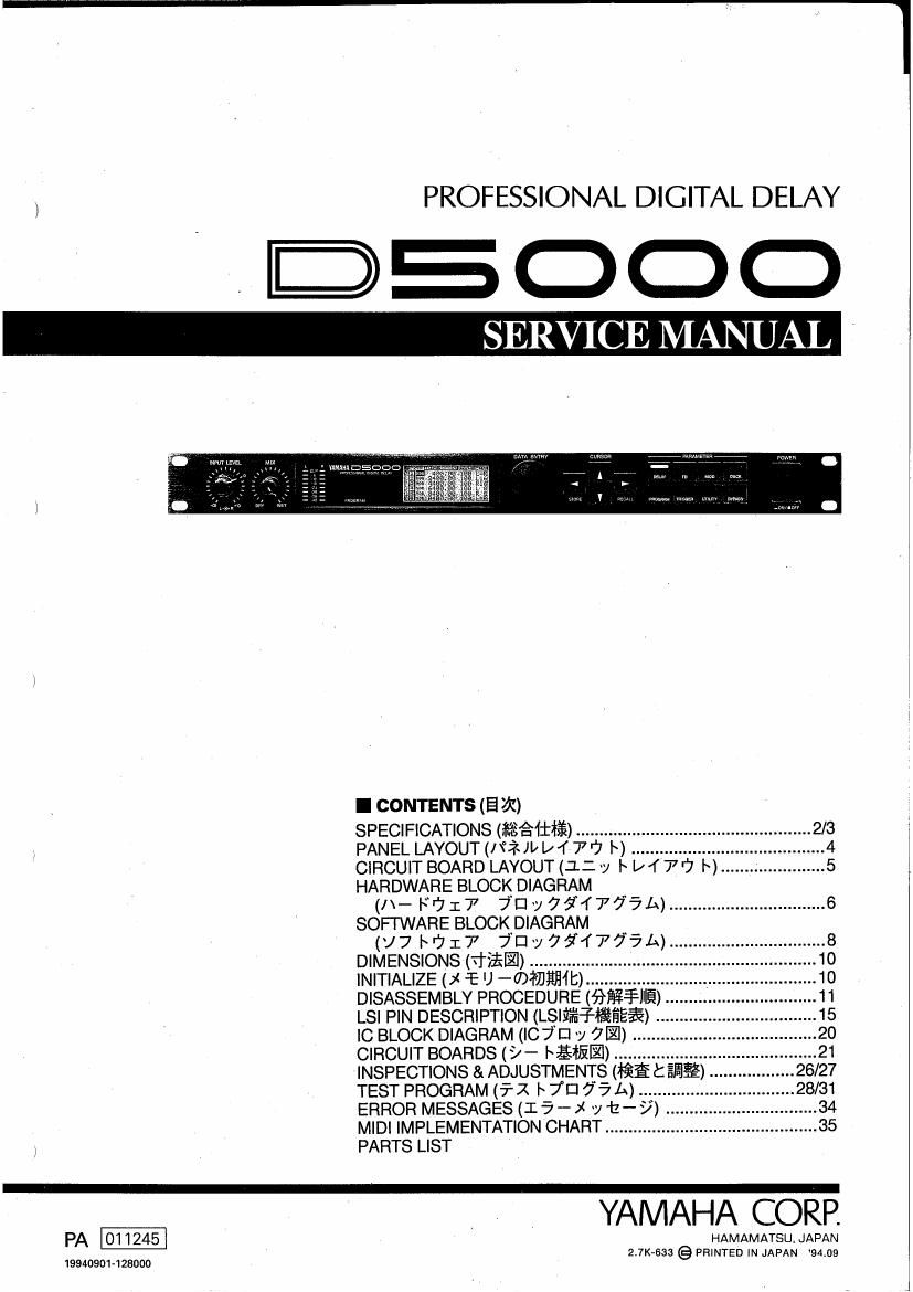
Yamaha d 5000

This is the 58 pages manual for yamaha d 5000.
Read or download the pdf for free. If you want to contribute, please mail your pdfs to info@audioservicemanuals.com.

Page: 1 / 58
left right
yamaha d 5000

Extracted text from yamaha d 5000 (Ocr-read)


Page 1

PROFESSIONAL DIGITAL DELAY

3500C)

SERVICE MANUAL

l CONTENTS (E m

SPECIFICATIONS (#3831125) ............................
PANEL LAYOUT (/\°in [/4 7 r? |~) ....................

CIRCUIT BOARD LAYOUT (1:. ~y I~ l/T 7r7 I~) ...................... 5
HARDWARE BLOCK DIAGRAM

(/x- F1717 7'Dv794775A) ................................. 6
SOFTWARE BLOCKDIAGRAM

(v7br7177 7Dy7fi4775h) ................................. 8
DIMENSIONS (vfiil) ................................... 10
INITIALIZE (x -'E U -<7)#7JHIIII:) ....................... 1o
DISASSEMBLY PROCEDURE (fifimfi). ..... 11
LSI PIN DESCRIPTION (Lsififafléfiéfi) ..... 15
IC BLOCK DIAGRAM (I07 III 'y 7.) .......... 20
CIRCUIT BOARDS (>- bgflil) ...................... 21
INSPECTIONS & ADJUSTMENTS Rafi t ESE) ....26/27
TEST PROGRAM (5-1 I 7D 75 A) ........... ....28/31
ERROR MESSAGES (I 5 - x v t- 9) . ..... 34
MIDI IMPLEMENTATION CHART ............................................. 35

PARTS LIST

PA-

19940901428000

YAMAHA CORP.

HAMAMATSU JAPAN
2.7K~633 @ PRINTED IN JAPAN 94.09

Page 2

D5000

l DISASSEMBLY PROCEDURE (fififllfi)

1 Top Cover_Removal 1 l~ J 7°71K-(D5i L73"
1-1 Remove the seven (7) screws marked [350], then 1.1 may»): yum? 1, )x yjjy/se-EM. L131,
the top cover can be removed. (Fig. 1) ([211)
[3501-430

[350]:BIND HEAD TAPPING SCREW-B(+I\4 / PB 5 cf I)A3.0X8 ZMCZBL(VP157000)

(Fio- 1)

2 Front Panel Assembly Removal . 2 7 El :1 MHULAss'yUMi L75

2-1 Remove the top cover. (see procedure 1) 2-1 l~ y 771 A-EM. Lira; (lifiéfifi)

2-2 Remove the two (2) screws marked [220], the three 2.2 [2201025 922:: 2: [230101 932i: e [260]«7)* 927:
(3) screws marked [230] and the two (2) screws {29(- LA 7 u y l~z<$IVAssy&5i-Lifio ([212)
marked [260], then the front panel assembly can be
removed (Fig. 2) 3 U 7/i*ILAss'y0)7l L73-

, 3-1 hyjfi/{raiafiibifn (lfiéfifi)

3 Rear Panel Assembly Removal 3.2 [5010* ~742s k [801096 922: 241301031 «722:2?

3-1 Remove the top cover, (see procedure 1) fibiao ([212)

3-2 Remove four (4) screws marked [50], the two (2) 3-3 [60]@/'i= 9923515)?!» 1" I) 7/<;?:/I/Ass'y&-7l» Li a;
screws marked [80] and the two (2) screws marked ([212)

[130]. (Fig.2) * U Tliiii/VAssyz5t3tt ADJ/W hwl<5~y

3-3 Remove the nine (9) screws marked [60], then the (filjfi-T: y 7 thieifij,

rear panel assembly can be removed. (Fig. 2)
* This will give you access to the pattern side of AD 4 ADD- F09} L75

circuit board. 4-1 i» y77J/<*-5:'51-L§T0 (1255*)
4-2 J 7/???»11/Assyéi5i 1/112, (3Gfiflfi)
4 AD Circuit Board Removal is y 71:;plvAsslyg5rt-a- g; \ AD~/~ l~ a)»; - y
4-1 Remove the top cover. (see procedure 1) (Rfléfi-x y 7 Efiéiéo
4-2 Remove the rear panel assembly. (see procedure 3) 4-3 [400]?)21 V871: a [40d]0)fi(~ 9223: l: [40e]®4§5§7<fi
' This will give you access to the pattern side of AD 'fy Milflifil-h ADVH |~ 75:51 Lid} (1213)

circuit board._

4-3 Remove the eight (8) screws marked [40c], the two
(2) screws marked [40d] and the six (6) hexagonal
nuts marked [4De], then the AD circuit board can be

. ' .3
11 removed (Flg )