Yamaha ct 1010

This is the 12 pages manual for yamaha ct 1010.
Read or download the pdf for free. If you want to contribute, please mail your pdfs to info@audioservicemanuals.com.

Page: 1 / 12
left right
yamaha ct 1010

Extracted text from yamaha ct 1010 (Ocr-read)


Page 2

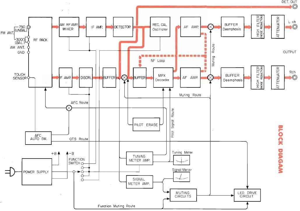
OUTLINE OF CIRCUIT As SHOWN SCHEMATIC DIAGRAM

FM FRONT END/IF

At the inlet. a double-tuning circuit is used. And a
dual-gate MOS type FET is employed for high frequen-
cy amplification and mixing. This FET has high input
impedance and small feedback capacity when compared
with a transistor, which are suitable for'high frequency
amplification and mixing. Thanks to the double-tuning
circuit and FET, outstanding selectivity, cross modu-
lation characteristics, low noise and high gain can be
obtained.

At the local oscillating section, IC is newly adopted
for producing stable oscillating frequency and output
voltage. .

intermediate frequency (iFi signal of 10.7MHz fed
from the front end is transmitted to I0201 for IF
amplification through VR201, and CFs 201 and 202.
Output from No. 5 pin if further transmitted to ICZOZ
amplitude limiter through CF203.

Generally, in the pass band of ceramic filter, undulation
of characteristics occurs. This undulation causes devi-
ation of phase of transfer frequency (FM modulated

factor), resuting in phase distortion at detection output.

To reduce such phase distortion, VR201 and T201 are
added to the inlets of CF'ZOi and CF202 respectively
to match the impedance. This circuit is called "phase
distortion compensating circuit."

The less. the better RIPPLE


BAND WIDTH _

3 '
d8
IO.7MH1

iF CENTER

Fig. 1 Band Pass Characteristics of Ceramic Filter

AFC/TUNING METER CIRCUIT

|0203 amplifies DC element of discrimination output
which TR203 and TR204 feed to No. 2 pin. This DC
element becomes zero when central frequency of IF is
10.7MH2 (perfect tuning) or when discrimination out-
put is zero at perfect detuning. When IF shift from
10.7MH2, signal including DC element corresponding
to shifting rate.

Part of amplified DC element is divided, and supplied
to the varicap diode of RF pack as AFC control voltage
in order to adjust the local oscillating frequency so
that IF becomes 10.7MHz (now DC element is zero)
at all times. At the same time, a pointer of tuning
meter swings by this voltage. When DC element of

discrimination output is zero, AFC voltage is also zero
and the pointer of meter reads the center. When DC
voltage is +, the pointer swings on + side, and when
DC voltage is -, the pointer swings on ~ side.

SIGNAL METER CIRCUIT

PM

At detuning, discrimination output delivered from
TR204 emitter contains noise signal with a wide band
frequency spectrum from low to high frequency. This
noise signal is transmitted to the base of TR220
through high~pass filters of 0275, C276, 0277, C279,
L208 and L209, and then amplified at TR220 and
TR219. The amplified signal is further rectified at
0207, and separated - voltage is returned to the base
of T8220 gets in OFF condition. in addition current
does not flow from the emitter to the signal meter, so
that the pointer of meter does not swing.

At tuning, amplified noise signal is small and voltage
which is returned to the base of TR220 is low, so that
TR is turned on. As a result, the current flows from
the emitter and the pointer of meter swings.

Basic operation of TR217 and TR218 is similar to
that of TR220 and TR219, then sensitivity of'meter
is further graded up due to functions of two circuits.

AM

When the voltage applied to D208 (7V of zenner
diode) exceeds 7V, yielding current flows and painter
or meter swings. in other words, D208 detects the
variation of collector voltage at TR229 as signal in-
tensity, and transmits it to the meter.

AUTO-TOUCH TUNING CIRCUIT

In case of tuning when AFC actuates, AFC activates
in the vicinity of tuning point, thus correct tuning
point being hardly distingushed.

To avoid this troubie, it is necessary to turn off AFC
when tuning is made. The auto-touch tuning circuit
automatically does that.

When the tuning knob is touched with finger, noise
factor catched by hLiman being is amplified at TR215
and TR216, and then half-wave rectified. As a result,
this noise factor emerges as + voltage. This + voltage
turns TR201 on, and earthes AFC route leading to the

RF pack. When the finger leaves the knob after tuning,
noise factor to be amplified is eliminated, so that

TR201 is turned off and earthing of AFC route is
released.