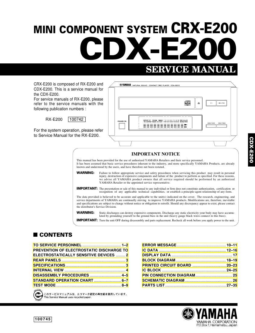
Yamaha crx e200

This is the 33 pages manual for yamaha crx e200.
Read or download the pdf for free. If you want to contribute, please mail your pdfs to info@audioservicemanuals.com.

Page: 1 / 33
left right
yamaha crx e200

Extracted text from yamaha crx e200 (Ocr-read)


Page 1

CDX-E200 CDX-E200 1 AC LEAKAGE TESTER OR EQUIVALENT EQUIPMENT UNDER TEST INSULATING TABLE WALL OUTLET CAUTION:USE OF CONTROLS OR ADJUSTMENTS OR PERFORMANCE OF PROCEDURES OTHER THAN THOSE SPECIFIED HEREIN MAY RESULT IN HAZARDOUS RADIATION EXPOSURE. THE COMPACT DISC PLAYER SHOULD NOT BE ADJUSTED OR REPAIRED BY ANYONE EXCEPT PROPERLY QUALIFIED SERVICE PERSONNEL. PROTECTION OF EYES FROM LASER BEAM DURING SERVICING This set employs a laser. Therefore, be sure to carefully follow the instructions below when servicing . 1. Laser Diode Properties  Material : GaAlAs  Wavelength : 780 nm  Emission Duration : Continuous  Laser Output : max. 44.6 µW* * This output is the value measured at a distance of about 200 mm from the objective lens surface on the Optical Pick-up Block. 2. When checking the laser diode emission, keep your eyes more than 30 cm away from the objective lens. Critical Components Information. Components having special characteristics are marked Z and must be replaced with parts having specifications equal to those originally installed.  TO SERVICE PERSONNEL WARNING: Laser Safety This product contains a laser beam component. This component may emit invisible, as well as visible radiation, which may cause eye damage. To protect your eyes and skin from laser radiation, the following precautions must be used during servicing of the unit. 1) When testing and/or repairing any component within the product, keep your eyes and skin more than 30 cm away from the laser pick-up unit at all times. Do not stare at the laser beam at any time. 2) Do not attempt readjustment, disassembly or repair of the laser pick-up, unless noted elsewhere in this manual. 3) CAUTION : Use of controls, adjustments or performance of procedures other than those specified herein may result in hazardous radiation exposure. Laser Emitting conditions: 1) When the Top Cover is removed, and the POWER SW is turned to the "ON" position, the laser component will emit a beam for several seconds to detect if a disc is present. During this time (5-10 sec.) the laser may radiate through the lens of the laser pick-up unit. Do not attempt any servicing during this period! If no disc is detected, the laser will stop emitting the beam. When a disc is set, you will not be exposed to any laser emissions. 2) The laser power level can be adjusted with the VR on the pick-up PWB, however, this level has been set by the factory prior to shipping from the factory. Do not adjust this laser level control unless instruction is provided elsewhere in this manual. Adjustment of this control can increase the laser emission level from the device. Optical Pick-up

Page 2

CDX-E200 CDX-E200 2 R, B, G models R, B, G models VARO! : AVATTAESSA JA SUOJALUKITUS OHITETTAESSA OLET ALTTIINA NÄKYMÄTTÖMÄLLE LASER-SÄTEILYLLE. ÄLÄ KATSO SÄTEESEEN. VARNING! : OSYNLIG LASERSTRÃ…LNING NÄR DENNA DEL ÄR ÖPPNAD OCH SPÄRREN ÄR URKOPPLAD. BETRAKTA EJ STRÃ…LEN. PREVENTION OF ELECTRO STATIC DISCHARGE (ESD) TO ELECTRO STATICALLY SENSITIVE (ES) DEVICES Some semiconductor (solid state) devices can be damaged easily by static electricity. Such components commonly are called Electrostatically Sensitive (ES) Devices. Examples of typical ES devices are integrated circuits and some field-effect transistors and semiconductor chip components. The following techniques should be used to help reduce the incidence of component damage caused by electro static discharge (ESD). 1. Immediately before handling any semiconductor component or semiconductor-equipped assembly, drain off any ESD on your body by touching a known earth ground. Alternatively, obtain and wear a commercially available discharging ESD wrist strap, which should be removed for potential shock reasons prior to applying power to the unit under test. 2. After removing an electrical assembly equipped with ES devices, place the assembly on a conductive surface such as aluminum foil, to prevent electrostatic charge buildup or exposure of the assembly. 3. Use only a grounded-tip soldering iron to solder or unsolder ES devices. 4. Use only an anti-static solder removal device. Some solder removal devices not classified as anti-static (ESD protected) can generate electrical charge sufficient to damage ES devices. 5. Do not use freon-propelled chemicals. These can generate electrical charges sufficient to damage ES devices. 6. Do not remove a replacement ES device from its protective package until immediately before you are ready to install it. (Most replacement ES devices are packaged with leads electrically shorted together by conductive foam, aluminum foil or comparable conductive material). 7. Immediately before removing the protective material from the leads of a replacement ES divice, touch the protective material to the chassis or circuit assembly into which the device will be installed. CAUTION: Be sure no power is applied to the chassis or circuit, and observe all other safety precautions. 8. Minimize bodily motions when handling unpackaged replacement ES devices. (Otherwise harmless motion such as the brushing together of your clothes fabric or the lifting of your foot from a carpeted floor can generate static electricity (ESD) sufficient to damage an ES device). Grounding for electrostatic breakdown prevention 1. Human body grounding. Use the antistatic wrist strap to discharge the static electricity from your body. 2. Work table grounding. Put a conductive material (sheet) or steel sheet on the area where the optical pickup is placed and ground the sheet. Caution: The static electricity of your clothes will not be grounded through the wrist strap. So take care not to let your clothes touch the optical pickup. 1M-„¦ Conductive material (sheet) or steel sheet Anti-static wrist strip The lavel is under the CD mechanism.