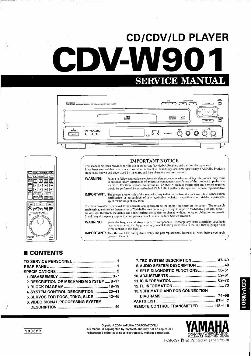
Yamaha cdv w901

This is the 102 pages manual for yamaha cdv w901.
Read or download the pdf for free. If you want to contribute, please mail your pdfs to info@audioservicemanuals.com.

Page: 1 / 102
left right
yamaha cdv w901

Extracted text from yamaha cdv w901 (Ocr-read)


Page 1

CD/CDV/LD PLAYER

CDV-W90 1

SERV E MANU

WWWA Wamm mmmmvst mm!

mm. #51:

(BTEQ

\ll
tillaé. i

are: n.
G

W)

I CONTENTS

TO SERVICE PERSONNEL .1 7. TBC SYSTEM DESCRIPTION.
REAR PANEL ...................... .1 8.AUDIO SYSTEM DESCRIPTION
SPECIFICATIONS .2 9. SELF-DIAGNOSTIC FUNCTIONS.
1. DISASSEMBLY . 3~7 10. ADJUSTMENTS
2. DESCRIPTION OF MECHANISM SYSTEM .. 8~17 11. IC INFORMATION 0
3. BLOCK DIAGRAM ............................. 18~19 12. FL INFORMATION ................................................ 73 U
4. SYSTEM CONTROL DESCRIPTION 13. SCHEMATIC AND PCB CONNECTION I<
5.SERVOS FOR FOCS, TRKG, SLDR ............. 42~45 DIAGRAMS .. 74~96 E
\ 6.VIDEO SIGNAL PROCESSING SYSTEM PARTS LIST ..... .97~117 8
.................. ................ 46 REMOTE CONTROL TRANSMITTER . 118~119 d

.l DESCRIPTION ....................

\ power to the unit.


IMPORTANT NOTICE

This manual has been provided for the use of authorized YAMAHA Retailers and their service pcrxonnel.
It has been assumed that basic service procedures inherent to the industry. and more specifically YAMAHA Products.
are already known and understood by the users. and have therefore not been restated.

WARNING: Failure to follow appropriate service and safety procedures when servicing this product may result
in perxonal injury. destruction of expensive components, and failure of the product to perform as
specified. For these reasons. we advise all YAMAHA product owners that any service required
should be performed by an authorized YAMAHA Retailer or the appointed service representative.

IMPORTANT: The presentation or sale of this manual to any individual or firm does not constitute authorization,
certification or recognition of any applicable technical capabilities. or establish a principle-
agent relationship of any form.

The data provided is believed to be accurate and applicable to the unit(s) indicated on the cover. The research.

engineering, and service departments of YAMAHA are continually striving to improve YAMAHA products. Modifi

cationx are. therefore. inevitable and specificationx are subject to change without notice or obligation to retrofit.

Should any discrepancy appear to exist, please contact the distributor's Service Division.

WARNING: Static discharges can destroy expensive components. Discharge any static electricity your body
may have accumulated by grounding younelf to the ground buss in the unit (heavy gauge black
wire: connect to this buss).

IMPORTANT: Turn the unit OFF during dISHhSClthy and patl replacement. Recheck all work before you apply

-

100529

Copyright 2004 YAMAHA CORPORATIOND
This manual is copyrighted by YAMAHA and may not be copied or [
redistributed either in print or electronically without permission.

YAMA

EgilllfijHAfoRPOR/K ION
. . x1, amamatsu, apan
1.65K-297 IE] Q0 Printed in Japan 95.10

Page 2

CDV-W90 1

I TO SERVICE PERSONNEL

Critical Components Informaticnl

Components having special characteristics are marked and
must be replaced with parts having specifications equal to those
originally installed.

WALL
OUTLET

AC LEAKAGE
EQUIPMENT TESTER OR
UNDER TEST EQUIVALENT

(DID-

J;

INSULATING
TABLE

CAUTION: USE OF CONTROLS OR ADJUSTMENTS OR PERFORMANCE OF PROCEDURES OTHER THAN THOSE
SPECIFIED HEREIN MAY RESULT IN HAZARDOUS RADIATION EXPOSURE.

THE COMPACT DISC PLAYER SHOULD NOT BE ADJUSTED OR REPAIRED BY ANYONE EXCEPT PROPERLY

QUALIFIED SERVICE PERSONNEL.

PROTECTION OF EYES FROM LASER BEAM DURING SERVICING

This set employs a laser. Therefore, be sure to carefully
follow the instructions below when servicing .

1. Laser Diode Properties

0 Material : GaAlAs

o Wavelength : 780 nm

0 Emission Duration: Continuous

0 Laser Output 2 max. 44.6 p.W*

* This output is the value measured at a distance
of about 200 mm from the objective lens surface
on the Optical Pick-up Block.

I REAR PANEL

2. When checking the laser diode emission, keep your
eyes more than 30 cm away from the objective lens.

7DIF

min .
69 mm

HH mm

wlrJt
alum am

e
@lEl
@o

Ilfltllflllllllltl mfiim E A&

m
92
m m z©©
®I' nae
I | '