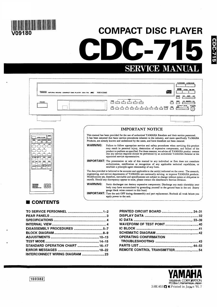
Yamaha cdc 715

This is the 52 pages manual for yamaha cdc 715.
Read or download the pdf for free. If you want to contribute, please mail your pdfs to info@audioservicemanuals.com.

Page: 1 / 52
left right
yamaha cdc 715

Extracted text from yamaha cdc 715 (Ocr-read)


Page 1

AIM

0Illllllllllllllllllll COMPACT DISC PLAYER

[:3 C: i 3

x; .7, i,iifid

new-o4
12m
mg . 2° . . .. _ -w-
Qmflfijm- mam
m __ :n-nmm-
Emma-ammmgamgz:

/

This mlmnl Ins been provided (a: the me of nuxhorized YAMAHA Rel-flex: and um service pasmnel.
I: has been assumed um basic sen-vice pmcedum Inhexmt to an industry. and more [Many YAMAHA
Prudums. an: already known Ind nude-mod by the um, Ind hm Iherdmc not been xesumd.

WARNING: Flam lo follow appropriate service and safely procadums when servicing this pmduc:
may Insult in puma! injury. denmcfim af expensive mpoumu, and failut: of the
pmducl to perform u specifitd. For thew masons, we advise .11 YAMAHA produc. ownexx
Lhn my service mqnimd should be perfumed by m lumofized YAMAHA Ream: or [he
lppoInlcd mm: mpmcnuuvc,

IMPORTANT: Th: prescnufmn or sale If this manual u: my individual a: film does nm amsLimle
amhnriudm, canificltim or recogniwion of any applicable technical upAbILLiu, m
mahlish a principlmgm xehtimship af my fmm.

m dau provided '5 beLicved to be accurate and nppliclble m the unMs) indicnwd on 11.: cover. 11.: match,

engineering, Ind :mice deplmnenu of YAMAHA are conu'nuauy sum; to improve YAMAHA cams.

Modifications Am, Lhacfom, inevinble and spwiflcllims are subject to dung: wilhoul notice or obligation lo

retrofit. Should my discmparwy appear m exist, plus: leacl the dinders Service Divuion.

mm [3mg WARNING: Sufi: dischuges can destmy expensive compmaxu. Dixchuge any made alwuidty ymu

mm body m-y have accumulucd by pounding younclf w Lh: gmund bass in the unii (heavy
gauge blnck wires comm m this buss).

IMPORTANT: Turn the uni! 0H7 during dinswmny and pan rephcanun. Rochcck All work bc'cxe you

K upply powex to the unit. /

IMPORTANT NOTICE \

I CONTENTS

TO SERVICE PERSONNEL .. 1~2
REAR PANELS .
SPECIFICATIONS .
INTERNAL VIEW...
DISASSEMBLY PROCEDURES ..
BLOCK DIAGRAM

ADJUSTMENTS .
TEST MODE .......
STANDARD OPERATION CHART . 16~17
ERROR MESSAGES .................... 18~22

INTERCONNECT WIRING DIAGRAM

PRINTED CIRCUIT BOARD ..
DISPLAY DATA

IC DATA .........
WAVEFORM OF TEST POINT.
IC BLOCK ............. . .....

SCHEMATIC DIAGRAM .
OPERATTNG CONFIRMATION
TROUBLESHOOTING ..
PARTS LIST.
REMOTE CONTROL TRANSMITTER

YAMAHA

YAMAHA CORPQRATION
no Box1Ha

3.0K-853n KIrinled m Japmawafun 91 7

9 lL'303

Page 2

CDC-715

I TO SERVICE PERSONNEL

1. Critical Components Information
Components having special characteristics are marked anm
must be replaced with parts having specifications equal to
those originally installed,

2. Leakage Current Measurement (For 120V Models Only).
When service has been completed, it is imperative to verify
that all exposed conductive surfaces are properly insulated
from supply circuits

0 Meter impedance should be equivalent to 1500 ohm shunted
by 0.15m:

a Leakage current must not exceed 0.5mA.

0 Be sure to test for leakage with the Ac plug in both
polarities

AC LEAKAGE
WALL EQUIPMENT TESTER on
OUTLET UNDER TEST EQUIVALENT
INSULATING T
TABLE

0 POLARIZATION (U, C modelI)
This CD player product is equipped with a polarized alternat-
ing-current line plug (a plug having one blade wider than the
other), This plug will fit into the power outlet only one way.
This is a safety feature.

CAUTION: USE OF CONTROLS OR ADJUSTMENTS OR PERFORMANCE OF PROCEDURES OTHER THAN THOSE
SPECIFIED HEREIN MAY RESULT IN HAZARDOUS RADIATION EXPOSURE.

THE COMPACT DISC PLAYER SHOULD NOT BE ADJUSTED OR REPAIRED BY ANYONE EXCEPT PROPERLY
QUALIFIED SERVICE PERSONNEL

PROTECTION OF EYES FROM LASER BEAM DURING SERVICING

This set employs a lasert Therefore, be sure to carefully
follow the instructions below when servicing I

1. Laser Diode Properties 2. When servicing, do not take the Optical Pick-up Block

0 Material :GaAlAs apart, and do not adjust the APC circuit. If there is a
o Wavelength :780 nm breakdown in the APC circuit (including the laser di-
0 Emission Duration : Continuous ode), replace the entire Optical Pick-up Block (includ-
0 Laser Output : max. 445 uW ing the APC board).

' This output is the value measured at a distance of
about 200 mm from the objective lens surface on
the Optical Pick-up Block.

3. When checking the laser diode emission, keep your
eyes more than 30 cm away from the objective lens

WARNING: CHEMICAL CONTENT NOTICE!

The solder used in the production of this product contains LEAD. In addition, other electrical/electronic
and/or plastic (where applicable) components may also contain traces of chemicals foUnd by the
California Health and Welfare Agency (and possibly other entities) to cause cancer and/or birth defects
or other reproductive harm.

DO NOT PLACE SOLDER, ELECTRICAL/ELECTRONIC OR PLASTIC COMPONENTS IN YOUR
MOUTH FOR ANY REASON WHATSOEVER!

Avoid prolonged, unprotected contact between solder and your skin! When soldering, do not inhale sol-
der fumes or expose eyes to solder/flux vapor!

If you come in contact with solder or components located inside the enclosure of this product, wash your
hands before handling food.