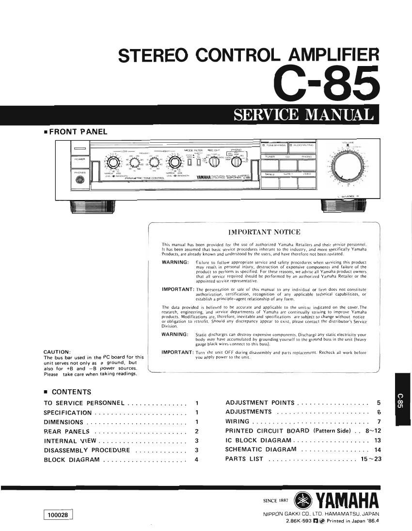
Yamaha c 85

This is the 23 pages manual for yamaha c 85.
Read or download the pdf for free. If you want to contribute, please mail your pdfs to info@audioservicemanuals.com.

Page: 1 / 23
left right
yamaha c 85

Extracted text from yamaha c 85 (Ocr-read)


Page 1

STEREO

I FRONT PANEL

- abanr-a

CONTROL AMPLIFIER

C-85

SERVICE MANUAL

This manual has

IMPORTANT NOTICE W

been provrdcd (or the use of Authorized Yamaha Retailers and their service personnel

It has been assumed that basic service procedures inhcram to rhc industry, and more specifically Yamaha
Products, are already known and understood by the users, and have therefore not been resralcdc

WARNING:

IMPORTANT:

Fatiurc to follow appropriate service and safety procedures when scrvlcing this product
may resuit tn occsonat iniury, dcstruction or expensive components and failure of the
product to perform as specified, For thcyc reasons, we advise all Yamaha product owners
that all service required should be performed hy an authorized Yamaha Retailer or the
appointed service VEDICSCnILttive,

The presentation or sale oi this manud) to any indtvldtlai or tlrm does not constitutc
authoridlion, certification, recognition of any applicable technical capabilititas, or
establish a princthe-agent relationship of any term.

The data provrded is believed to be accurate and applicable to the whim indicated on the cover.The
research, engineering, and service departments or Yamaha are contrnuany strrvlng to improve Yamaha
products Modifications are, therefore, incvirable and schtIications an: subject to change without "cute

or obligation to

Division.
WARNING:
i
CAUTION: IMPORTANT:
The bus bar used in the PC board for this
unit serves not only as a ground, but ,
also for +8 and -5 power sources. k
Please take care when taking readings. ____,7
I CONTENTS
TO SERVICE PERSONNEL t .. ....... .a . ..
SPECIFICATION ........
DIMENSIONS . .......... . . . . t ..... . . .,
REARPANELS, ...... .....
INTERNAL VIEW ....... ...,, ...... . . .r
DISASSEMBLY PROCEDURE t . . . . a . . .....
BLOCK DIAGRAM .... ....... .... ......

retrofit, Should any dtscrcpartcv appear to exist, please contact the distributor's Service

Static discharges can destroy expensive components. Dlschargc any static ctcctncity your
body may have accumulated by grounding yoursett to thc ground huts m the unit lheavy
gauge black wrrcs connect to this buss),

Turn tho unit OFF during disassembly and parts reniacemcnt. Rechcck all work hctorc
you apply power to the unil. t

1 ADJUSTMENT POINTS .......... . t . . . c a . 5
1 ADJUSTMENTS ....... . ,. . . . . ...... . 6
1 WIRING. .......... ..... 7
2 PRINTED CIRCUIT BOARD (Pattern Side) . t 8~12
3 IC BLOCK DIAGRAM. ........ 13
3 SCHEMATIC DIAGRAM . .......... . . . . . . 14
4 PARTSLIST. ........... ..t...t.15~23

$ YAMAHA

NIPPON GAKKI CO, LTD HAMAMATSUJAOAN
2.86K-593 w Primed in Japan 85.4

980