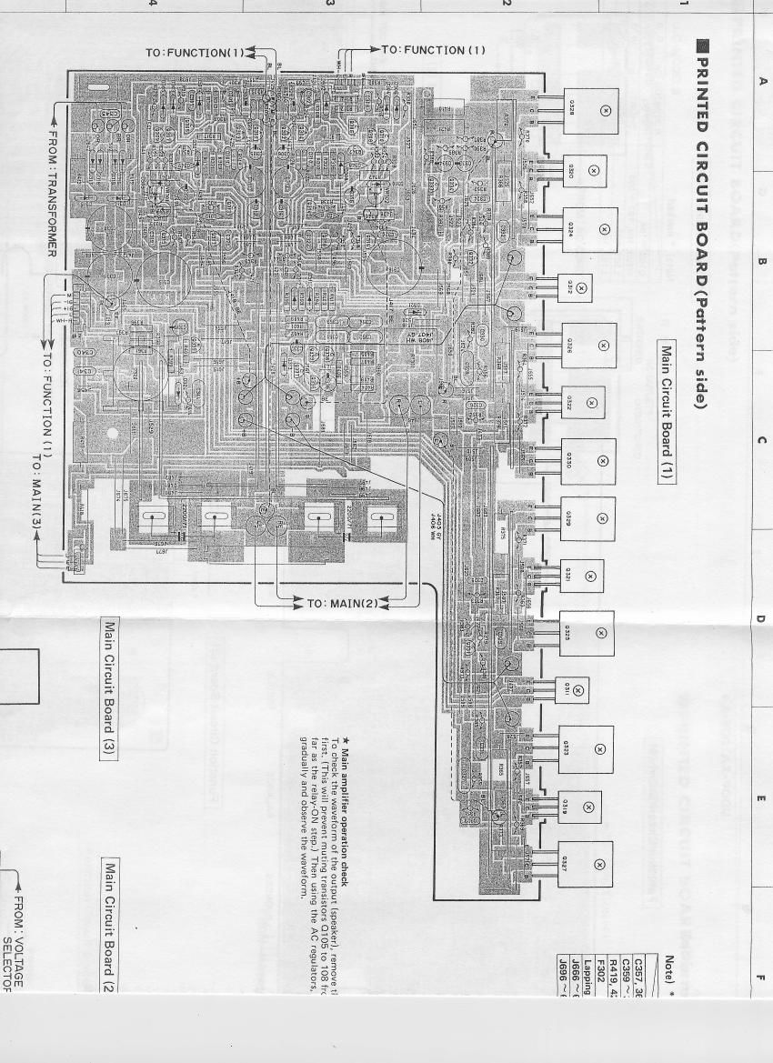
Yamaha ax 900 schematic

This is the 14 pages manual for yamaha ax 900 schematic.
Read or download the pdf for free. If you want to contribute, please mail your pdfs to info@audioservicemanuals.com.

Page: 1 / 14
left right
yamaha ax 900 schematic

Extracted text from yamaha ax 900 schematic (Ocr-read)


Page 2

Note) * marked

\ R u, c 5 A G, a

c357, 3e ,364 OPEN OPEN \ OPEN _ 0.01
c359 ~ 362 OPEN OPEN \ OPEN 5? HOOP/100
3419, 420 -* OPEN OPEN 1 OPEN 47

F302 T5.0A 250v OPEN 5 OPEN OPEN
Lapping Terminal SET NONSET 1 NONSET NONSET
K1666 ~669 OPEN OPEN SHORT SHORT
Jase ~599 OPEN OPEN SHORT SHORT

Main Circuit Board (Bil

PHONES

FROMzMAINH )VLU

it Main amplifier operation check

To check the waveform Of the Output (speaker), remove the diode 0312
first. (This will prevent muting transistors 0105 to 108 from operating as

far as the relay»ON step.) Then using the AC regulators, appiy
graduaHv and observe the waveform.

WaiiLCircuit Board (2?

FROM I VOLTAGE
SELECTOR

FROM: MAINH)

voltage

* ®

SPEAKERS


L


4,

FROM 2 MAINH)

SPEAKERS
A B