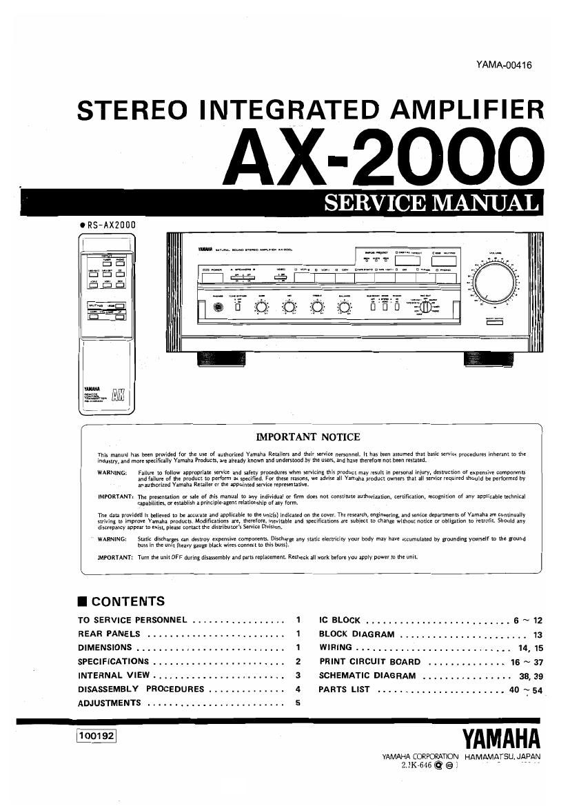
Yamaha ax 2000

This is the 59 pages manual for yamaha ax 2000.
Read or download the pdf for free. If you want to contribute, please mail your pdfs to info@audioservicemanuals.com.

Page: 1 / 59
left right
yamaha ax 2000

Extracted text from yamaha ax 2000 (Ocr-read)


Page 1

YAMA-004 1 6

STEREO INTEGRATED AMPLIFIER

AX-2000

SERVICE MANUAL

I RS-AXZUUD

n- m-

m. .m. m. a .a w ...:." '-
T :2 r, a in?
76 E?" fir F

IMPORTANT NOTICE

This manuil has been provided for It: use OI aumu'ized Yamaha Reuilzrs and thnir service personnel. I! has bun assumed that baslc service procedures inhenn! Lo me
induslxy, and more specifically Yamaha Preducts. an already known and understood W the users, and have merefure not been restated.

WARNING: Failure In follaw appropriate seerDc and safety procedures when servicing INS pruducr may result In persunal injury, desvucficn of expensive components
and failura of (In product to perform as specifmd. For these reasons, we advise all Yamaha product owners that all service requlrcd should be parlormed by
an aumoriled Yamaha Retailer 0r r11: appoinmd Beryl representative.

IMPORTANT: The prescnlzfinn or sale of this manual In any Individual or firm does no! constitute authorization, ccmflcation. recognition of any applicable wchnical

capabilities. or esrabllsh aprinclple-agzm mlakinnship nf any (own.

The diva providb'd IS beliwed m be mum: and applicable to file an ndicawd on We cover. The research, cngintefing, and 59le depamncms of Yamaha are wnlinuzlly
striving to improve Vamaha praducs. Mudificalions are, therefore, inevitable and specifications are subject to Change without notice or obligation to 'retmfiL ShouId any
discrepancy app!" to exisL plus: conmt the distributor's Stwlce Division.

WARNING: Sufi: dlstharys can «may expensive compmem Discharge my sud: elezwichy your body may hay: accumulated by guarding yourself r0 me yound

buss In me unit (hzavy gauge black wires mum: to this buss).
IMPORTANT: Turn the unizoFF during disassembly and pans replacement. Recheck all work before you zpply power to Iii: unit.

I CONTENTS

DISASSEMBLY PROCEDURES . . . . . . . . . . . . . .
ADJUSTMENTS

PARTSLIST

40754

TOSERVICEPERSONNEL...v............. 1 ICBLOCK..........................6~12
REARPANELS 1 BLOCKDIAGRAM.......................13
DIMENSIONS........................... 1 WIRING 14,15
SPECIFICATIONS........................ 2 PRINTCIHCUITBOARD ............16~37
' |NTERNALV|EW..... 3 SCHEMATICDIAGRAM 38,39
4
5

YAMAHA

VAMAHA (:02me HAMAMATSU. JAPAN
2.1K-646@@]

Page 2

AX-2000

I TO SERVICE PERSONNEL

1. Critical Components Information, ' EQU|PMENT AC LEAKAGE TESTER
Components having special charaexerisrics are marked ' UNDEH TEST 0R EQUIVALENT
and must be replaced with parts having specifinations equal

to those originally installed -, ® E

2. Leakage Current Measurement (For 120V Modal Only)
When servlce has been completed ix is impermlve that you WALL 1:!
verify that I" exposed conductive surfaces are properly OUTLET =
insulated from supply clrcuits.

INSULATING TABLE

o Meter impedance should be cquwalem to 1500 ohm shunted
bv 0.15IIF

o Leakage current must not exceed 0.5mA.

a Be sure to test for leakage wish the AC plug in born polarities.

I REAR PANELS

. W MODEL 8
E-OOOCOOE ®
®
0 R MODEL ®
®
«3 31-99999???
ob doOQdédéOdédéééw
-O O°O®OOOOWOQ®OO®°
-: @\
Ems-Tr: " ."- n.
® WW GOGOOO-w

IDIMENSIONS
\
III
oI
l0:
FlFlFlFl
5 in
V 2
I2: l2: 3 -
I::I EH: l T
:1: Ell: '0 In
l:ll::l El: 3 :
:12! EH: .0 m
l:ll=l l=ll=l $ I;
:1: I:l:l r
l=ll=| I2: is
l:ll:l :II:I :
I:II:I :Ir:l g
5
N
l_l
:~ r
I:II:I a, 2
, O =°Eo
OIIOOODnI-Io A9:
=' _. B
|__l | I
e
O
a
1 473 (N
'2