Yamaha a 400

This is the 10 pages manual for yamaha a 400.
Read or download the pdf for free. If you want to contribute, please mail your pdfs to info@audioservicemanuals.com.

Page: 1 / 10
left right
yamaha a 400

Extracted text from yamaha a 400 (Ocr-read)


Page 1

r:~"}-

II ,

/ V _ . HM

STEREO INTEGRATED AMPLIFIER

Afi© ©

SERVICE MANUAL

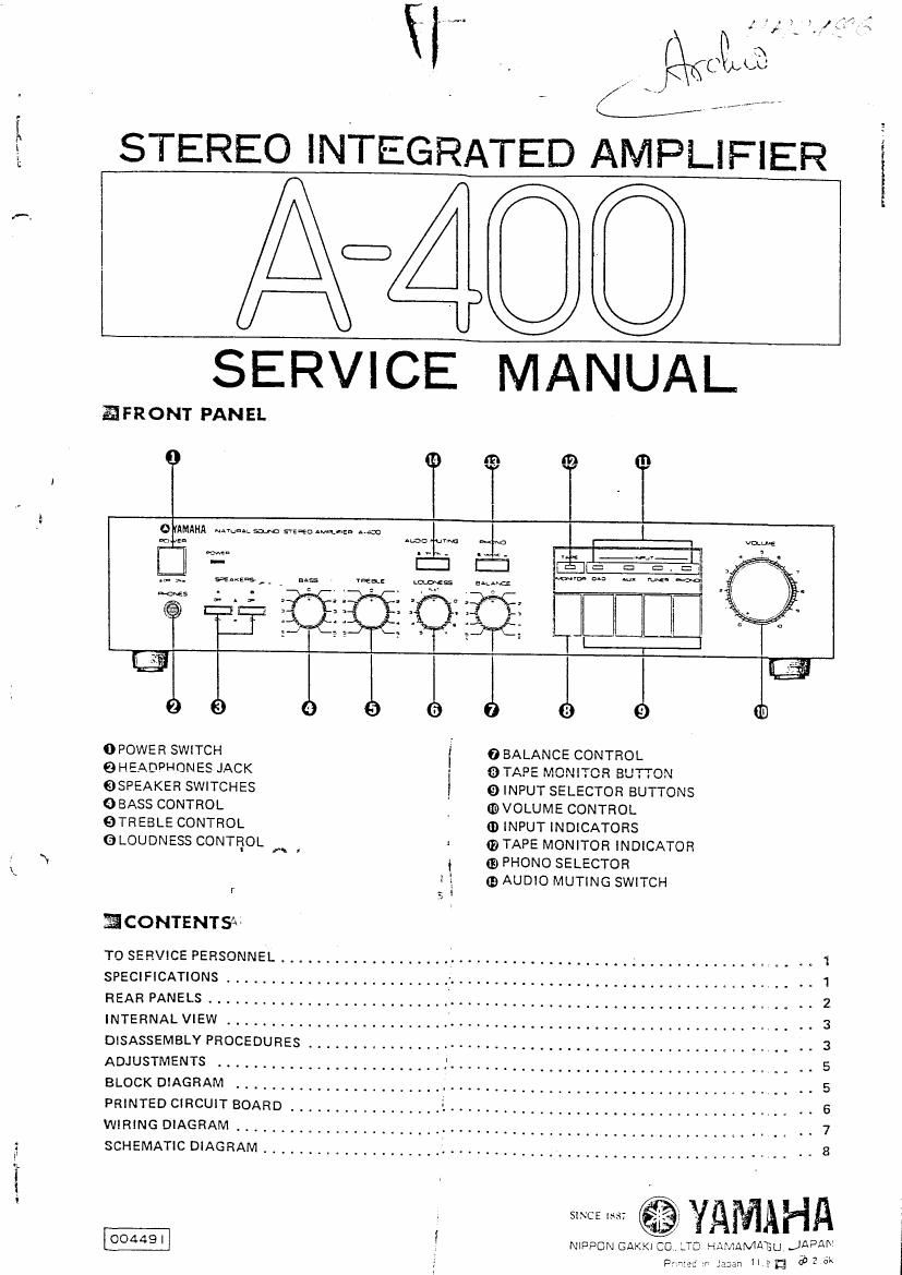
EFRONT PANEL

NAYIfiA; 51m STEBEO an... can

0 POWER SWITCH

0 HEADPHONES JACK
@SPEAKER SWITCHES

0 BASS CONTROL

@TREBLE CONTROL
GLOUDNESS CONTROL A .

r

ECONTENTSN

To SERVICE PERSONNEL .............

0 BALANCE CONTROL
QTAFE MONITOR BUTTON
9 INPUT SELECTOR BUTTONS

(EVOLUME CONTROL
0 INPUT INDICATORS
I 0 TAPE MONITOR INDICATOR

I mPHONO SELECTOR
I Q AUDIO MUTING SWITCH
I

....... * 1
SPECIFICATIONS ......................... > ....................................... 1
REAR PANELS ___________________________ I ....................................... 2
INTERNAL VIEW ......................... ' ....................................... 3
DISASSEMBLY PROCEDURES ....................................................... 3
ADJUSTMENTS ................................................................. 5
BLOCK DIAGRAM ............................................................... 5
PRINTED CIRCUIT BOARD ................. i ...................................... .. e
WIRING DIAGRAM ............................................................. ~ 7
SCHEMATIC DIAGRAM .................... i ...................................... - 8

@I YAMAHA

NIPPON GAKKCO TD HAMAMAISLIJAPAA:
'Ilasan "133 3;: 5k

Page 2

A-4OO

TO SERVICE PERSONNEL ,3

(Prepared in accordance with UL Standard 1270)
Before service of this appliance by you, please carefully read this service manual.

Please make Leakage-current or Resistance measurements by suitable meter to determine that exposed
pans are acceptably insulated from the supply circuit before returning the appliance to the customer.

LEAKAGE CURRENT MEASUREMENT CIRCUITS

GH
(GROUNDIN
OPEN

APPLIANCE

=0:

METER

.4355

6) E
INSULATING
TABLE

GROUND SUPPLY CONDUCTOR

Appliance intended for connection to a 120 volt power supply.

A PROBE WITH SHIELDED LEAD.
B SEPARATED AND USED AS CLIP WHEN MEASURING CURRENTS FROM
ONE PART OF APPLIANCE TO ANOTHER.

Confirm that the leakage current is not more than 0.5mA

SPECIFICATIONS,

Continuous Power Per Channol
20H: ~20kHz

Residual Noisu (lHF-A-Network)
Channel Separation

less than ZOOuV

(0.015% THD, 851) 40W Phono MM, AUX, Tape 40H: SBdB
(Hz (0.006% THD,8fll 45W (H2 EDdB
DIN Standard Output Power 10kHz GDdB

Per Channel
lkHZ (1% THD, 89.)

50W IGHBHAI

Tone Control Characteristics
Bass boost/cut

i10dB lat 50Hz)

Power Bandwidth Bass turnover frequency SSOHI

0.05% THD, 20W (89) 10H: ~40kHz TrEble boost/cut 1 10:18 (at 20kHzl
Damping Factor . Treble turnover frequency 3,5kHz

(at lkHz, 8n) better than 37 ' Continuous Loudness Control
Maximum Input Signal Level (Level-related equalization)

Fhana MC IOmV , Attenuation 20413 (at 1kHzl

MM 180mV 3 Audio Muting -2053

Output Level/Impedance .= Gain Tracking Error (0 ~-EOdBl 3d8

RecOut 150mV/47on 5 Power Supplies
Headphone Jack Rated Output] ' U.S.A. and Canadian models AC 120V, 60Hz
lmpdaneo (LEV/100$! General model

Frequency Response
AUX, Tape, Tuner

20H: ~20kHz, -0.2clB

l

European model

AC110/120/220/2dflv
SDISOHZ

AC220V, 50H:
RIAA Equalization Deviation British and Australian models AC24DV, 50H:
Phono MC 1 0.5dB Power Consumption
MM 1* 0.3.13 ; U.S.A. model 150w
Total Harmonic Distortion , Canadian model 160w
Phono MC to Rec Out (RV! 0.01% g General model 160w
MM to Rec Out (8V) 0.007% : British, Australian and European
AUX, Tape, Tuner to Sp Out 3 models 220W
ROW/8(2) 0.015% AC Outlet
Intarmodulation Distortion Switched x 2 100W max.
AUX, Tape, Tuner Rated Unswitched x 1 200W max.
Output/BIZ 0.02% Dimensions (WxHxD) 435 x 92 x 293mm
SIInaMo-Nois- Ratio I17-1/8x3~5/8111<1/2|"
(IH ilk-Network) 5.3kg (1 1.7 lbs)
Pheno MClsoouv, Input shorted) mas/nae «31 {Km
MMlsmv, Input shorted) BZdE/BOdB (Gl Amil/'8" model only.
AUX, Tape, Tuner [Input shorted) 9MB European model only.
Siaml-m-Naiso Ratio (New IHF) , 5"th model only.
Phano MC 7MB Specifications subject to change without notice.
MM 7BdB i
A ux, Tape, Tuner aoaa
l

l