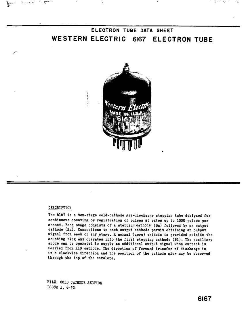
Western electric 6167 brochure

This is the 4 pages manual for western electric 6167 brochure.
Read or download the pdf for free. If you want to contribute, please mail your pdfs to info@audioservicemanuals.com.

Page: 1 / 4
left right
western electric 6167 brochure

Extracted text from western electric 6167 brochure (Ocr-read)


Page 1

_ 1.0,...

ll

ELECTRON TUBE DATA SHEET .
WESTERN ELECTRIC 6l67 ELECTRON TUBE

DESCRIPTION

The 6167 is a ten-stage cold-cathode gas-discharge stepping tube designed for
continuous counting or registration of pulses at rates up to 1000 pulses per
second. Each stage consists of a stepping cathode (En) followed by an output
cathode (Kn). Connections to each output cathode permit obtaining an output
signal from each or any stage. A normal (zero) cathode is provided outside the
counting ring and operates into the first stepping cathode (Bl). The auxiliary
anode can be operated to supply an additional output signal when current is
carried from K10 cathode. The direction of forward transfer of discharge is

in a clockwise direction and the position of the cathode slow may be observed
through the top of the envelope.

FILE: com) CATHODE SECTION
ISSUE 1, 6-52

6l67

Page 2

6167 - Page 2

RATINGS, Absolute Values

Cathode Current

Maximum Peak -------------- 10 milliamperes
Maximum Average ------------ 3 milliamperes
Minimum Average ------------ .l milliampere
Maximum Averaging Time --------- 0.5 second
Maximum Inverse Anode or Auxiliary Anode Current 0.0 milliampere
Ambient Temperature Limits ----- - - - -55 to +60 centigrade

ELECTRICAL DATA]-

Min. Eogez Max.

Anode Voltage Drop - - - $ --------- --- 110 --- volts
Anode Breakdown Voltage

Output Cathodes and Normal Cathode - -

- 180 225 300 volts

Stepping Cathodes (Bl-BIO) - - - ----- 150 190 250 volts
Auxiliary Anode

Voltage Drop to Cathode K10 ------- --- 112 --- volts

Breakdown Voltage ----------- - 260 300 --- volts

Transfer Voltage 2 to Cathode K10 - - - - See Curve
Transfer Voltage 2. 3- to any Cathode
except K10 - - - - - - - - - - - ~ - - - 260 290 --- volts

Cathode

Forward Transfer VoltageA - - - - - - ~ - --- -10 -20 volts
Transfer Voltage Between Adjacent Output

Cathodes5v 6 - - - - - - - - - - - - ~ - -L5 --- --- volts
Transfer Voltage Between Normal Cathode and

Output Csthodee6 - - - - - - - - - - - - -30 .-- --- volts

MECHANICAL DATA

Mounting Position-- - - - - - - - - - ----------- - - Any
Bulb------------ ------------------ T9
Dimensions and pin connections shown in outline on Page L

Note 1

Note 2

Note 3

Note A

Note 5

All data are based on operation of the tube within average current
ratings at the time of stepping or transfer of the discharge. -

Voltage, with respect to an operating cathode, at which conduction
occurs from the auxiliary anode to cathode indicated.

Measured with maximum K10 voltage of +50 volts with respect to the
operating cathode.

Voltage, with reapect to an operating cathode, applied to the adjacent
forward cathode to transfer the discharge to that cathode.

Measured under static conditions. This is an absolute limit on output
voltage but as frequency of operation is increased, the available output
voltage is decreased because of residual ionization in the preceding
cathodes.