Western electric 384 a 385a brochure

This is the 10 pages manual for western electric 384 a 385a brochure.
Read or download the pdf for free. If you want to contribute, please mail your pdfs to info@audioservicemanuals.com.

Page: 1 / 10
left right
western electric 384 a 385a brochure

Extracted text from western electric 384 a 385a brochure (Ocr-read)


Page 1

BELL SYSTEM PRACTICES SECTION AB46.640
Transmission Engineering and Data Issue 1, August 1941
Vacuum Tube Data A T & T Co Standard

Wafer/7 Electric

384A and 385A Vacuum Tubes

384A 385A
Classification-~Voltage Amplifier. Suppressor-Grid Pentodes with Indirectly Heated
Cathodes
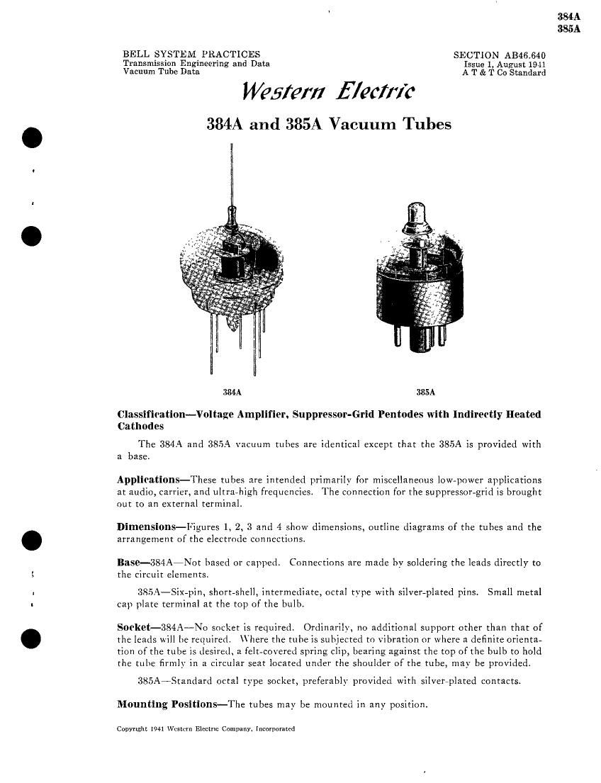
The 384A and 385A vacuum tubes are identical except that the 385A is provided with

a base.

Applications-These tubes are intended primarily for miscellaneous lowapower applications
at audio, carrier, and ultra~high frequencies. The connection for the suppressor-grid is brought
out to an external terminal.

Dimensions-Figures 1, 2, 3 and 4 show dimensions, outline diagrams of the tubes and the
arrangement of the electrode connections.

Base-384A7Not based or capped. Connections are made by soldering the leads directly to
the circuit elements.
385A-Six-pin, short-shell, intermediate, octal type with silver-plated pins. Small metal

cap plate terminal at the top of the bulb.

Socket-384A-No socket is required. Ordinarily, no additional support other than that of
the leads will be required. here the tube is subjected to vibration or where a definite orienta~
tion of the tube is desired, a felt-covered spring clip, bearing against the top of the bulb to hold
the tube firmly in a circular seat located under the shoulder of the tube, may be provided.

385A~Standard octal type socket, preferably provided with silvereplated contacts.
Mounting Positions-The tubes may be mounted in any position.

Copyright 1041 \Vcstcrn Electric Company, Incorporated

384A
385A

Page 2

384A
385A

Average Direct Inter-Electrode Capacitances

3.3L _33_5é__
ControLgrid to plate ........................ 0.02 0.02 ppf
Control-grid to heater, cathode, screemgrid and
suppressor-grid ........................ 3.1 3.6 ,up.f
Plate to heater, cathode, screen-grid and sup-
pressor-grid ............................ 2.1 2.4 puf

384A-The control-grid to plate capacitance is measured with the tube resting in a circular
seat consisting of a one-inchediameter hole in a metal sheet located under the shoulder of the
tube. The metal sheet is connected to the cathode of the tube.

No shielding is used in the measurement of the input and output capacitances.

385A-The control-grid to plate capacitance is measured with the tube in an octal wafer
socket located approximately one-half inch above a metal sheet. A close fitting metal shield
is placed around the bulb and base of the tube and connected, together with the metal sheet,
to the cathode. The lead from the control-grid terminal of the socket is brought through a
small opening in the metal sheet.

No shielding or socket is used in the measurement of the input and output capacitances.

Heater Rating
Heater voltage ............................ 6.3 volts, are or d-c
Nominal heater current .................... 0.15 ampere

The heaters of these tubes are designed to operate on a voltage basis and should be oper-
ated as near the rated voltage as practicable.

Cathode Connection-Where alternating heater voltage is used, the cathode should pre-
ferably be connected directly to the mid-point of the heater transformer winding or to the
mid-point of a low resistance connected across the heater terminals. For direct current opera-
tion the cathode may be connected to either end of the heater. If voltage is applied between
the heater and cathode, it should be kept low and must not exceed 50 volts.

Characteristics-Figures 5 and 6 show plate current and screen-grid current characteristics
of typical tubes as functions of control-grid voltage for several values of screen-grid and plate
voltage and zero suppressor-grid voltage. The screen-grid voltage for these characteristics is
equal to the plate voltage. Figures 7, 8 and 9 show corresponding amplification factor, plate
resistance. and transconductance characteristics. Figures 10 and 11 show plate current and
screen-grid current characteristics as functions of plate voltage for three values of control-grid
voltage, a screen-grid voltage of 120 volts, and zero suppressor-grid voltage. Figures 12, 13
and 14 show corresponding amplification factor, plate resistance, and transconductance
characteristics.

Limiting Conditions for Safe Operation

Maximum plate voltage .................. 250 volts
Maximum screen-grid voltage ................. 120 volts
Maximum suppressor-grid voltage ............. 120 volts
Maximum cathode current (total space current). 12 milliamperes
Maximum screen-grid current ................. 5 milliamperes

Operating Conditions and Output-Nominal performance data are given in the table
below for a number oftvpical operating conditions. Since the life of the tubes may be shortened
when operated under the maximum conditions, less severe conditions should be selected where-
ever possible.

The performance data include the fundamental power output and the second and third
harmonic levels for the indicated values of load resistance and input voltage. The power
output is given in dbm (decibels above one milliwatt), and the harmonic levels in decibels
below the fundamental.

l2]