Western electric 375 a brochure

This is the 6 pages manual for western electric 375 a brochure.
Read or download the pdf for free. If you want to contribute, please mail your pdfs to info@audioservicemanuals.com.

Page: 1 / 6
left right
western electric 375 a brochure

Extracted text from western electric 375 a brochure (Ocr-read)


Page 1

BELL SYSTEM PRACTICES SECTION AB46.375A
Transmission Engineering Data Issue 1, May 1950
Vacuum Tube Data A.T.&T. Co. Standard

PENTODE W512! Electric

DESCRIPTION
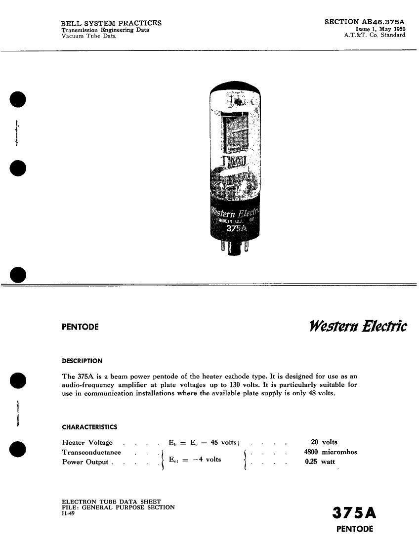
The 375A is a beam power pentode of the heater cathode type. It is designed for use as an

audio-frequency amplifier at plate voltages up to 130 volts. It is particularly suitable for
use in communication installations where the available plate supply is only 48 volts.

CHARACTERISTICS

Heater Voltage . , . . El, : E0 = 45 volts; . , . . 20 volts
Transconductance . . _ . . . . 4800 micromhos
Power Output . . . . , E : 4 VOIts . . . . 025 watt

ELECTRON TUBE DATA SHEET

FILE: GENERAL PURPOSE SECTION
11.49 3 7 5 A

PENTODE

Page 2

375A - PAGE 2

GENERAL CHARACTERISTICS

ELECTRICAL DATA

Heater Voltage, A-C or D-C
Heater Current . . . . . . . . . . .
Direct Interelectrode Capacitanees (without external shield)
Grid to Plate
Input .
Output

MECHANICAL DATA

Cathode

Bulb

Base . .
Mounting Position

20.0 volts
320 tnilliamperes

1.0 uuf
13.5 uuf
8.5 uuf

Coated Unipotential

T11

Medium shell, 6-pin octaI

Any

Dimensions and pin connections shown in outline drawing on Page 6

MAXIMUM RATINGS, Design-Center Values

Plate Voltage . .

Screen Grid Voltage .
Maximum Signal Plate Current .
Plate Dissipation .
Screen Grid Dissipation .

130 volts

130 volts

50 milliamperes
6 watts

13 watts

Maximum Grid Circuit Resistance for
Fixed Bias .
Cathode Bias .

TYPICAL OPERATING CONDITIONS AND CHARACTERISTICS

Plate Voltage . . . . . . . . . . . . 45
Screen Grid Voltage . . . . . . . . . . 45
Control Grid Voltage . . . . . . . . . . --4
Peak A-F Grid Voltage . . . . . . . . . 4
Zero Signal Plate Current . . . . . . . 12.5
Maximum Signal Plate Current . . , . . . . 13.8
Zero Signal Screen Grid Current . . . . . . 1.5
hiaximum Signal Screen Grid Current . . . . . 4.0
Transconductanee . . . . . . . . . . . 4800
Plate Resistance . . . . . . . . . . . 9300
Load Resistance . . . . . . . . . . . 2800
Maximum Signal Power Output . . . . . . . 0.25

Total Harmonic Distortion . . . . . . . . 10

90
90
-75
7.5
33
34
3.7
11.7
6600
7800
2500
1.4

8

0.1 megohrn
0.5 megohm

120 volts

120 volts
-12 volts

12 volts

34 milliamperes

37 milliamperes
3.7 milliarnperes
19.0 milliarnperes
6200 micromhos
8000 ohms
2500 ohms

2.5 watts

14 per cent