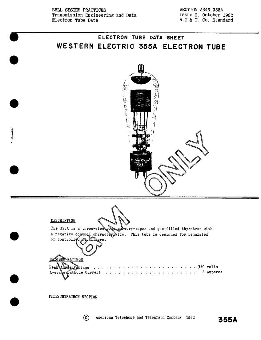
Western electric 355 a brochure

This is the 4 pages manual for western electric 355 a brochure.
Read or download the pdf for free. If you want to contribute, please mail your pdfs to info@audioservicemanuals.com.

Page: 1 / 4
left right
western electric 355 a brochure

Extracted text from western electric 355 a brochure (Ocr-read)


Page 1

BELL SYSTEM PRACTICES SECTION AB46.355A
Transmission Engineering and Data Issue 2, October 1962
Electron Tube Data A.T.& T. C0. Standard

ELECTRON TUBE DATA SHEET
WESTERN ELECTRIC 355A ELECTRON TUBE

DESCRIPTION

The 355A is a three-else

cury-vapor and gas-filled thyratron with
. a negative co ficharact ,1, tie. This tube is designed for regulated
or controll fie .

................ 350 volts

L amperes

FILE : THYRATRON SECTION

© American Telephone and Telegraph Company 1962

355A

Page 2

3551 - Page 2
IAXIHUE RATINGS, ABSOLUTE VALUES

Peak Anode Voltage

Inverse . . . . . . . . . . . . . . . . . . . . . . . . . . . . 350 volts

Forward . . . . . . . . . . . . . . . . . . . . . . . . . . . . 350 volts
Cathode Current

Peek . . . . . . . . . . . . . . . . . . . . . . . . . . . . . 16 amperes

Average . . . . ...... . . . . . . . . . . . . . . . . . . h amperes

Surge (maximum duration 0.1 second) . . . . . . . . . . . . . . 160 amperes

AveragineTime ..155econda
Negative Grid Voltage

Before Conduction . . . . . . . . . . . . . . . . . . . . . . . 100 volts

. . . . . . . . . 10 volts

During Conduction . . . . . . . . . .

Positive Grid Current, Average
(Averaging time - one cycle) . . . .

Equilibrium Condensed Mercury Temperature
Rise Above Ambient
At Full Load, Approximate . . . . . .
At No Load, Approximate . . . . . . .
Mounting Position . . . . . . . . . . . .
Net Height, Approximate . . . . . . . . .

Dimensions and pin connections shown in outline

. . . 0

.050 aepere

Condensed Mercury Temperature Limits ........... -55 to +80 centigrade
ELECTRICAL DATA
M .3130 e E:

Filament Voltage . . . . . . . . . . . . . . . . 2.37 2.5 2.62 volts
Filament Current at 2.5 Volts . . . . . . . . . ---- 16 17.5 amperes
Filament Heating Time Required . . . . . . . . . L5 ---- ---- seconds
Anode to Grid Capacitance . . . . . . . . . . . ---- 1.L ---- uuf.
Grid to Filament Capacitance . . . . . . . . . . ---- B ---- nuf.
Deionization Tine, Approximate

Ebb'350 volts:Ib-16 amperes;

Ecc--15 volts; THg-BOC;Rg-20000 ohms . . . . ---- 3000 ---- microseconds
Ionization Time. Approximate

Ebb-100 volts:TEg-h00;0rid 0vervoltsge-5 volts ---- 15 ---- microseconds

Ebb-100 volts;TEg-BOC;Grid Overvoltage-ZS volts ---- l ---- microseconds
Anode Voltage Drop . . . . . . . . . . . . . . . ---- 15 ---- volts
Critical Grid Current at 220 Anode Volts . . . . ---- --v-- 5 microamperss
Change in Critical Grid Voltage at

350 Anode Volts from +20 to +80 THg . . . . --~~ 0.2 -e-- volt
MECHANICAL DATA
Type of Cooling . . . . . . . . . . . . . . . . . . . . . . Convection

25 centigrade
15 csntigrade

Vertical - base down

drawing on Page A

8 ounces

1. For starting conditions only. Equilibrium operation is limited to +200

2.

minimum condensed mercury temperature.

Deionization time decreases with an increase in negative grid voltage

or with a decrease in (a) condensed mercury temperature (Tfig), (b) grid
resistance or (c) anode current immediately preceding the end of conduction.
Ionization time decreases with an increase in (a) anode voltage, (b) condensed
mercury temperature (Tfig) or (c) grid overvoltege. Grid overvoltage is
defined as the magnitude by which the applied voltage exceeds, in a positive
direction, the critical grid voltage value. Critical grid voltage is the
instantaneous value of grid voltage at the time when anode current starts to
flow.