Western electric 337 a brochure

This is the 6 pages manual for western electric 337 a brochure.
Read or download the pdf for free. If you want to contribute, please mail your pdfs to info@audioservicemanuals.com.

Page: 1 / 6
left right
western electric 337 a brochure

Extracted text from western electric 337 a brochure (Ocr-read)


Page 1

BELL SYSTEM PRACTICES SECTION ABL6.337A
Transmission Engineering and Data 155? 1, April 1951
Electren Tube Data A.T.&. T. 00. Standard

ELECTRON TUBE DATA SHEET
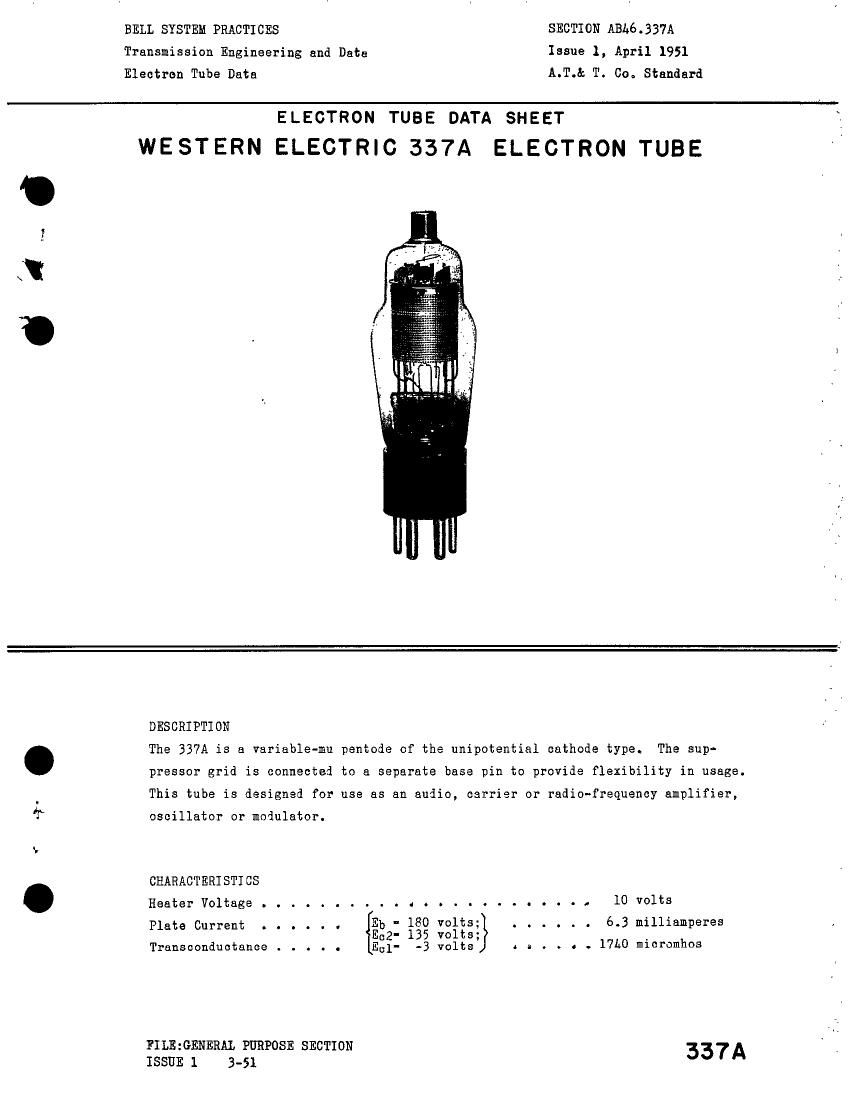
WESTERN ELECTRIC 337A ELECTRON TUBE

Id

DESCRIPTION

. The 337A is a variable-mu pentode of the unipotential cathode type. The sup-
pressor grid is connected to a separate base pin to provide flexibility in usage.

. This tube is designed for use as an audio, carrier or radio-frequency amplifier,

13* oscillator or modulator.

»
CHARACT ERI STI CS

. HeaterVoltage....................... lOvolts

5332- 135 volts;

E31- -3 volts 4 a . . o . 17h0 micromhos

Plate Current . . . . . . {Eb ' 180 V°lt8;} . . . . . . 6.3 milliamperes

Transconductance . . . . .

FILE:GENERAL PURPOSE SECTION
ISSUE 1 3-51 337A

Page 2

337A - Page 2

GEKERAL CHARACTERISTICS

ELECTRICAL DATA
Heater Voltage, A-C or D-C . . . .
Heater Current . . . .......

Direct Interelectrode Capacitances

Grid to Plate (maxinum). . . .
Input. . . . . . . . . . . . .
Output . . . . . . . . . . . .

With external shield (RMA#311)

MECHANICAL DATA

Cathode. . . . . . . . . . . . . .
Bulb . . . . . . . . . . . o . . .
Base . . . . . . . . . . . . . . .

Mounting position . . . . . . . .

Dimensions and pin connections shown

- 0

Connected

10 volts

. 320 millianperes

WITHOUT WITH EXTERNAL

EXTERNAL s ELD

0.01 *0'.009 u'uf
5.9 * 6.5 uuf
12.h 13.0 uuf

to Cathode (Pin 9

. . . . . Coa

. . . . . . STl

. . . . . Sma

. . . . . . . . . . . . . Any

KAXIMUM RATINGS, DESIGN-CENTER VALUES

Plate Voltage . . . . . . . . . .
Screen Grid Voltage . . . . . . .
Plate Dissipation . . . . . . . .
Screen Grid Dissipation . . . . .
Cathode Current . . . . . . . . .
Heater-Cathode Voltage . . . . . .

TYPICAL OPERATIEG CONDITIONS AND CHARACTERISTICS

Plate Voltage . . . . . . . . . . . . .

Screen Grii Voltage . . . . . . .
Control Grid Voltage . . . . . , -
Suppressor Grid Voltage . . . . .
Plate Current . e . . . . . . . .
Screen Grid Current . . . . . . .
Peak A-F Signal Voltage . . . . .
Plate Resistance . . . . . . . . .
Transconiuctance . . . . . . . . .
Loai Resistance . . . . . . . . .
Power Cutput . . . . . . . . . .
Total Harmonic Distortion . . . .
Control Grii Voltage (aporoximate)
Transconiuctance o 10 micrombos .

for

135
135
-3

0
6.2
1.3
3.0
0.55
1730
30000
230
6.0

-18.5

in outline drawing on

1
L

. . . . . . 2

. . . . . . 1

. . . . . . 0
. . . . . . l
180 250
135 135
-3 -3
0 0
6.3 6.35
1.27 1.2L
1.5 2.0
0.85 1.16
17L0 1750
00000 100000
150 300
7.0 8.0 _

~18.5 -18.5

5)

ted unipotential
2
ll 6-pin

Page 5

50 volts
80 volts
2 watts
.A watt
10 millianperes
50 volts

volts

volts

volts

volts
milliamperes
nilliamperes
volts
megohms
nicromhos
ohms
milliwetts

Q".