Western electric 329 a brochure

This is the 8 pages manual for western electric 329 a brochure.
Read or download the pdf for free. If you want to contribute, please mail your pdfs to info@audioservicemanuals.com.

Page: 1 / 8
left right
western electric 329 a brochure

Extracted text from western electric 329 a brochure (Ocr-read)


Page 1

311A

329A
BELL SYSTEM PRACTICES SECTION AB46.585
Transmission Engineering and Data Issue 1, August 1939
Vacuum Tube Data A T & T Co Standard

Western fleet/12

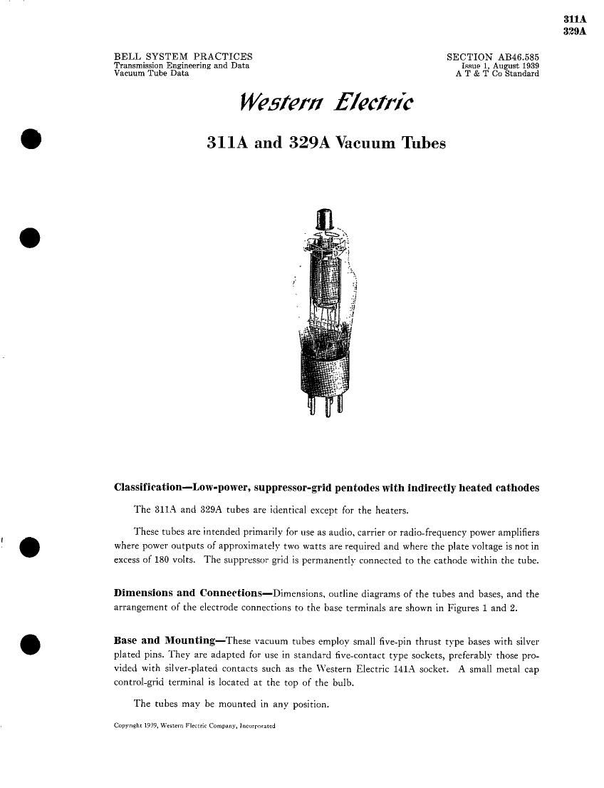
311A and 329A Vacuum Tubes

Classification-Low-power, suppressor-grid pentodes with indirectly heated cathodes
The 311A and 329A tubes are identical except for the heaters.

These tubes are intended primarily for use as audio, carrier or radio-frequency power amplifiers
where power outputs of approximately two watts are required and where the plate voltage is not in
excess of 180 volts. The suppressor grid is permanently connected to the cathode Within the tube.

Dimensions and Connections-Dimensions, outline diagrams of the tubes and bases, and the
arrangement of the electrode connections to the base terminals are shown in Figures 1 and 2.

Base and Mounting-These vacuum tubes employ small five-pin thrust type bases with silver
plated pins. They are adapted for use in standard five-contact type sockets, preferably those pro-
vided with silver-plated contacts such as the Western Electric 141A socket. A small metal cap
control-grid terminal is located at the top of the bulb.

The tubes may be mounted in any position.

Copyright 1939, Western Flcciric Company, Incorporated

Page 2

311 A
329A

Average Direct Inter-electrode Capacitances

Controlgridtoplate .. . .. .. .. .. .
Control grid to heater, cathode and screen grid.
Plate to heater, cathode and screen grid. . . .....
Column AiWithout shield.
Column BiWith close fitting metal shield connected to the cathode.

Heater Ratings
3llA Tube 329A Tube

Heater voltage. . . . . . . . . . 10.0 7.5 volts, a.c. or d.c.

Nominal heater current . i . ..... . . . 0.64 0.85 ampere

The heaters should be operated on a voltage basis and at as near the rated voltage as

practicable.

The voltage between the cathode and the heater should not exceed 150 volts.

Characteristics-Figures 3 and 4 respectively, show plate current and screen-grid current as
functions of control-grid voltage for several values of screen and plate voltage. In all curves the
plate voltage is equal to the screen voltage. Amplification factor, plate resistance and transcon-
ductance curves for the conditions corresponding to those of Figures 3 and 4 are given respectively
in Figures 5) 6 and 7.

Plate current and screen-grid current are shown as functions of plate voltage in Figures 8 and
9 respectively, for a screen-grid voltage ot185 volts and for several values of control-grid voltage.
Corresponding curves for amplification factor, plate resistance and transconductance are given in
Figures 10, 11 and 12 respectively.

Curves showing the fundamental power output and the second and third harmonic levels as
functions of input voltage for a number of values of load resistance for typical operating conditions

are given in Figures 13. 14 and 15 respectively.

Limiting Conditions for Safe Operation

Maximum direct plate voltage. . . . . . 180 volts
Maximum direct screen-grid voltage . . . . . . ....... . . 150 volts
Maximum cathode current (plate current plus screen-grid current) 60 milliamperes
Maximum direct screen-grid current . . ............. . 12 milliamperes

Operating Conditions and Output - Nominal performance data are given in the table
on page 3 for a number of typical operating conditions. Less severe operating conditions should be
selected in preference to the maximum conditions wherever possible. The life of the tube at maxi-
mum conditions will be shorter than at the less severe conditions.

The performance data include the fundamental power output for the indicated values of load
resistance and input voltage, and the maximum second and third harmonic levels for input voltages
not exceeding the indicated values. Under certain conditions the maximum second harmonic level
occurs at a lovver input voltage than that given in the table. The power output is given in warts,
and the harmonic leVels in decibels below the fundamental.

[-71

-r