Western electric 313 a brochure

This is the 4 pages manual for western electric 313 a brochure.
Read or download the pdf for free. If you want to contribute, please mail your pdfs to info@audioservicemanuals.com.

Page: 1 / 4
left right
western electric 313 a brochure

Extracted text from western electric 313 a brochure (Ocr-read)


Page 1

313A

BELL SYSTEM PRACTICES SECTION AB46.595
Transmission Engineering and Data Issue 1. September 1936
Vacuum Tube Data A T & T Co Standard

Wafer/7 flecfr/c

313A Vacuum Tube

3
§
E

a
i

Classification-Double gap, cold cathode, gas-filled tube for use as a relay, rectifier or voltage
regulator in special circuits.

The elements of the 313.-\ tube consist of two similar control electrodes and one anode. The
conduction path between the control electrodes is known as the control gap. The conduction path
between either control electrode and the anode is known as the main gap.

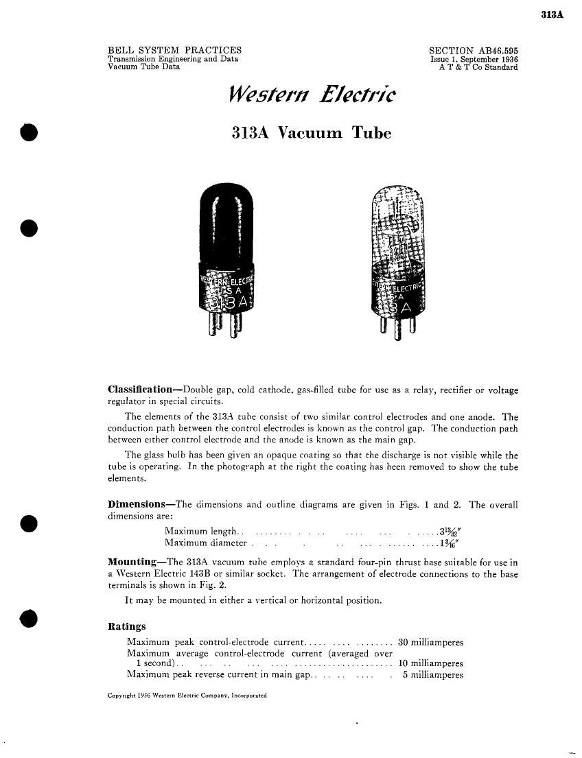
The glass bulb has been given an opaque coating so that the discharge is not visible while the
tube is operating. In the photograph at the right the coating has been removed to show the tube
elements.

Dimensions-The dimensions and outline diagrams are given in Figs. 1 and 2. The overall
dimensions are:

Maximum length. . ........ . . .. .... ... . ..... 31%
Maximum diameter . . . . .. ... . ...... ....13716

Mounting-The 313A vacuum tube employs a standard four-pin thrust base suitable for use in
a Western Electric 1433 or similar socket. The arrangement of electrode connections to the base
terminals is shown in Fig. 2.

It may be mounted in either a vertical or horizontal position.

Ratings
Maximum peak control-electrode current ..... . . , . ........ 30 milliamperes
Maximum average controlvelectrode current (averaged over
1 second). . ... .. ... .... ..................... 10 milliamperes
Maximum peak reverse current in main gap. . . . . . . . . . 5 milliamperes

Copyright 1936 Western Electric Company, Incorporated

Page 2

313A

Characteristics
Nominal control gap breakdown voltage . . , . . . . . 70 volts
Nominal control gap sustaining voltage . . . . . . . . . . 60 volts
Nominal main gap breakdown voltage . . . , . 175 volts
Nominal main gap sustaining voltage. . . . . . . 75 volts
Transfer current . . . . . . . . . . . . . . . . . . 5 microamperes (max.)
Nominal deionization time
Main gap . . . . .. . . . .. ..... .. . .. . .. . 10 milliseconds
Control gap. . , . , . .. , ..,. . . ....... 3 milliseconds

The maximum peak control-electrode current is the maximum value of current which may
be drawn from either control electrode when it is acting as a cathode.

The maximum average control-electrode current is the maximum value of current (averaged
over 1 secondI which may be drawn from either control electrode when it is acting as a cathode.

The maximum peak reverse current in the main gap is the maximum value of current which
may be drawn from the anode in the reverse direction. that is when it is acting as a cathode. The
reverse current rating is intended for use in designing rectifier circuits and is the maximum inverse
current which it is permissible to draw from the tube in such circuits.

The control gap breakdown voltage" is the potential required to initiate ionization, thereby
starting conduction in the control gap. Once ionization has occurred the potential across the gap
will be reduced to the control gap sustaining voltage" and will be approximately independent
of the current, It is this property of the tube which enables it to be used as a voltage regulator.

The main gap breakdown voltage" is the potential required to start conduction in the main
gap when no ionization is occurring in the control gap. After breakdown, conduction will take
place at the main gap sustaining voltage and will be practically independent of current.

The main gap sustaining voltage is substantially independent of current when the current
passes through the tube in the forward direction. When the current passes through the main gap
in the reverse direction the sustaining voltage increases rapidly with increasing current. It is this
asymmetry in the properties of the main gap of the 313A tube which enable it to be used as a
rectifier. The current voltage characteristics of the main gap of a typical 313A tube in both forward
and reverse directions as shown in Fig. 3. This curve was obtained with a cathode ray oscillograph.

When the anode potential is maintained at a value intermediate between the main gap break-
down and sustaining voltages" the passage of a small amount of current in the control gapwill
produce ionization sufficient to initiate conduction in the main gap. It is this property of the tube
which enables it [0 be used as a relay. The amount of current in the control gap required to initiate
conduction in the main gap is known as the transfer current. This quantity varies considerably
from tube to tube and during the life of a given tube but will in general be less than 5 microamperes
and usually only a few tenths of a microampere.

The deionization time is the time during which the voltage must be removed from the tube in
order that the discharge shall not be reestablished when the voltage is restored. This time increases
with increasing applied voltage and with increasing current through the tube before the deioniza-
tion period. This rate of increase of deionization time is such that the tube will not deionize with
a 60 cycle sine wave main gap voltage if the load is inductive or if the peak voltage is near the
main gap breakdown voltage or the current near the maximum rated value.

The transfer time is the time during which the control gap must be energized in order that
the discharge may transfer to the main gap. It depends upon the amount of current flowing in
the control gap and on the main gap voltage. For a control gap current of 10 microamperes the
transfer time" is approximately 200 microseconds.

[2]