Western electric 311 b brochure

This is the 4 pages manual for western electric 311 b brochure.
Read or download the pdf for free. If you want to contribute, please mail your pdfs to info@audioservicemanuals.com.

Page: 1 / 4
left right
western electric 311 b brochure

Extracted text from western electric 311 b brochure (Ocr-read)


Page 1

BELL SYSTEM PRACTICES
Transmission Engineering and Data
Electron Tube Data

ABI+6. 3113
Issue 1, 10-60
A.T. & T. Co. Standard

ELECTRON TUBE DATA SHEET

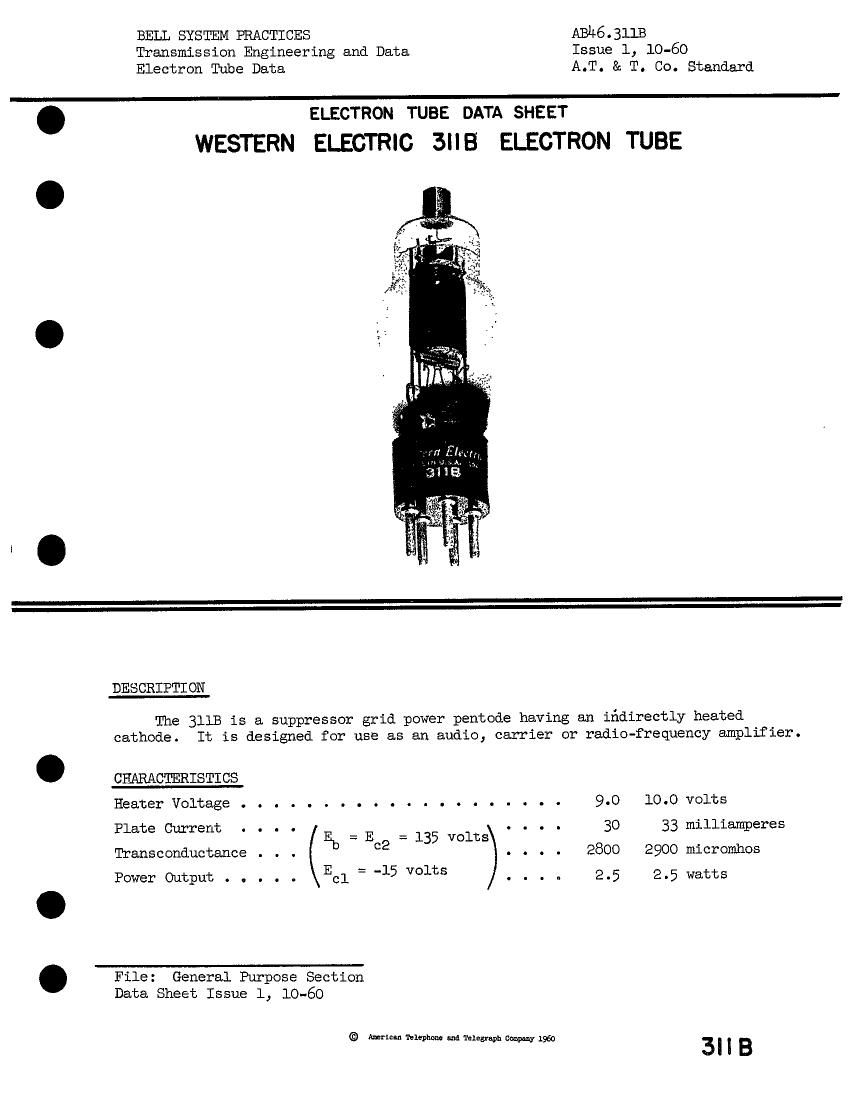
WESTERN ELECTRIC 3MB ELECTRON TUBE

DES CRIPTI ON

The 311B is a suppressor grid power pentode having an ifidirectly heated
cathode. It is designed for use as an audio, carrier or radio-frequency amplifier.

CHARACTERISTICS
Heater Voltage . . . . . . . . . . . . . . . .
Pl te Currert . . . .

a L Eb=E2=l35 volts
Transconductance . c

Power Output . . . . . Ecl = -15 Volts

File: General Purpose Section
Data Sheet Issue 1, 10-60

© Americln Telephone and Telegraph Company 1960

9.0 10.0 volts

3O 33 milliamperes
2800 2900 micromhos
2.5 2.5 watts

3I|B

Page 2

3MB - PAGE 2

331313.41 CIARACTERZSTICS
Electrical Data
Heater Voltage, A-C or D-C (Note 1). . . . . . . . 9.0 10.0 volts
HeaterCurrent..................0.60 0.64ampere .
Direct Interelectrode Capacitances without with
external shield external shield
(RMA #311)
..................O.32 0.09npf
..................8.0 9.5upf
85 10.#ppr
..................... Coatedunipotential
.. STJ2
Base.......................... Small,5pin
I~iountingPosition.................... Any
Dlmensions and pin connections shown in outline drawing on Page 1+

.-iaxi::'.zm Bangs, Absolute System (Note 2)

Plate Voltage. . . . . . . . . . . . . . . . . . . . . . 200 volts

Screen Grid Voltage. . . . . . . . . . . . . . . . . . . 150 volts
PlateDissipation. . . . . . . . . . . . . . . . . . . . 9.0mtts

creen Grid Dissipation. . . . . . . . . . . . . . . . . 1.8 watts
CathodeCurrent..................... 60miuiamperes .
Heater-Cathode Voltage . . . . . . . . . . . . . . . . 150 volts
TYPICAL OPERATING CONDITIONS AND CHARACTERISTICS

Single Tube Amplifier - Class A

Heater "'oltage . . . . . . . . . . . . 9.0 10.0 10.0 volts

Plate Voltage . . . . . . . . . . . . 135 135 180 volts

Screen Grid Voltage . . . . . . . . . 135 135 135 volts

Control Grid Voltage . . . . . . . . . -15 -15 -15 volts

Peak A-F Grid Voltage. . . . . . . . . 15 15 15 volts

Zero Signal Plate Current. . . . . . . 3O 33 31+ milliamperes

Maximum Signal Plate Current . . . . . 33 36 38 milliamperes .
Zero Signal Screen Grid Current. . . . 6.3 6.5 6.0 milliamperes

Maximum Signal Screen Grid Current . . 11.5 11.0 10.0 milliamperes
Trensconductance . . . . . . . . . . . 2800 2900 3000 micromhos

Plpte Resistance . . . . . . .
Load Resistance . . . . . . .
Maximum Signal Power Output. .
'Iotpl Harmonic Distortion. . .

Notel: For optimum tube life, a
However, when 9 volts is

Note 2: In the Absolute System"

. . . . #5000 #0000 #7000 ohms

. . . . 3500 3500 #000 ohms

. . . . 2.0 2.0 2.8 watts

. . . . 10.0 9.0 10.5 per cent .

heater voltage of 9 volts is recommended.
used, it must be regulated to i- l.

the maximum ratings specified are limiting .

values above which the serviceability of the device may be impaired
from the viewpoint of life and satisfactory performance. Maximum

ratings, as such, do not

constitute a set of operating conditions

and all values may not, therefore, be attained simultaneously.