Western electric 310 a brochure

This is the 6 pages manual for western electric 310 a brochure.
Read or download the pdf for free. If you want to contribute, please mail your pdfs to info@audioservicemanuals.com.

Page: 1 / 6
left right
western electric 310 a brochure

Extracted text from western electric 310 a brochure (Ocr-read)


Page 1

BELL SYSTEM PRACTICES

ABAG.310A
Transmission Engineering and Data Issue 2, February 1956
Electron Tube Data

A.T.&T. Co. standard

ELECTRON TUBE DATA SHEET
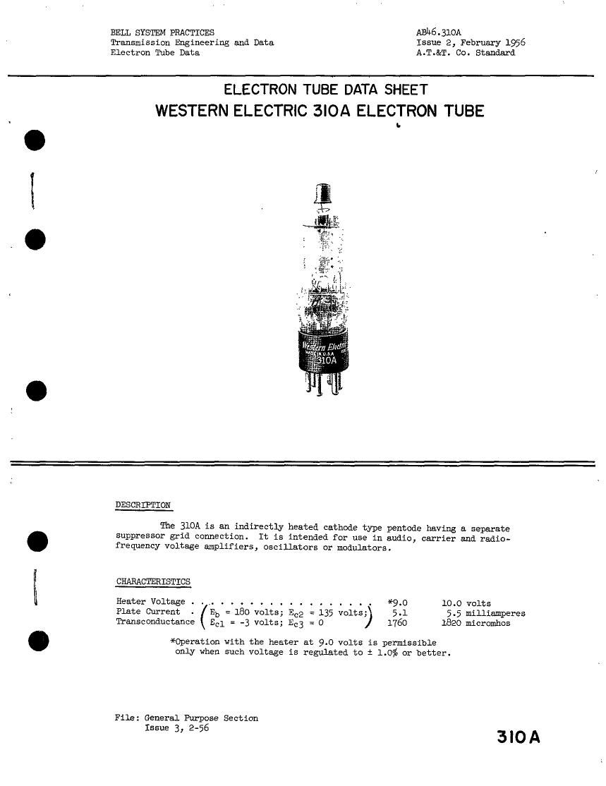
WESTERN ELECTRIC 3IOA ELECTRON TUBE

DESCR IPTION

The 310A is an indirectly heated cathode type pentode having a separate
suppressor grid connection.

It is intended for use in audio, carrier and radio-
frequency voltage amplifiers, oscillators or modulators.

CHARACTERISTICS

Heater Voltage . . .. . . . ...... . . . . . . . *9.0 10.0 volts

Plate Current Eb = 180 volts; Ecg = 135 volts; 5.1 5.5 milliamperes
Transconductance Ecl = -3 volts; E3 = O 1760 1820 micromhos

*Operation with the heater at 9.0 volts is permissible

only when such voltage is regulated to i 1.0% or better.

File: General Purpose Section
Issue 3, 2-56

3|OA

Page 2

- e 2

GENERAL CHARACTERISTICS

ELECTRICAL DATA a
Heater Voltage . . . . . . . . . ...... . 9.0 10.0 volts
Heater Current . . . ...... . . A . . 300 320 milliamperes
Direct Interelectrode Capacitances . . . without with
external external shield
shield (3311le #311)
Grid to Plate (maximum) . . . . . 0.016 *0.010 upf
Input: $1 to (h+k+g2+g3+i 3.). . . 6.0 *7.0 nnf
tput: p to (h+k+g2+g3+i.s.). . . 13 *13 puf
MECHANICAL DATA
Cathode . . . . . . . . . . . . . . . . . . . . . . . . . Coated unipotential
Bulb . . . . . . . . . . . ....... . . . . . . . . STlZ
Ease . . . . . . . . . . ..... . . . . . . . . Stall 6-pin
Mounting Position . . . . . . . . . . . . . . . . . . Any

Dimensions and pin connections shown in outline drawings on page 5

MAXIMUM RATINGS, Design-Center Values

Plate Voltage . . . . . . . . , . . . . . . . . . . . . . . 250 volts
Screen GridVoltege . . . . . . . . . . . . . . . . . . . 180 volts
Plate Dissipation . . 1 . . . . . . . . . . . . . . . . . . 2.0 watts
Screen Grid Dissipation . . . . . . . . . . . . . . . . . . O.h watt
Cathode Current . . . i . . . . . . . . . . . . . . . . . . 10 milliamperes
Heater-Cathode Voltage . . . . . . . . . . . . . . . . . 150 volts
TYPICAL OPERATING CONDITIONS AND CHARACTERISTICS
Heater Voltage . . . . . . . . . . . . . . 10.0 10.0 10.0 volts
Plate Voltage . . . . . . . . . . . . . . 135 180 250 volts
Screen Grid Voltage . . . . . . ..... 135 135 135 volts
Control Grid Voltage . . . . . . . . . . . -3 -3 -3 volts
Suppressor Grid Voltage . . . . . . . . . 0 O 0 volts
Plate Current . . . . . . . . . . . . . . 5.h0 5:50 5.60 millianyeres
Screen Grid Current . . . . . . . . . . . 1.20 1.18 1.17 milliemperes
Peak A-F Signal Voltage . . . . . . . . . 3.00 1.50 2.10 volts
Plate Resistance . . . . . . . . . . . . . 0.75 0.90 1.15 megohms
Transconductance . . . . . . . . . . . . . 1800 1320 lBhO micromhos
Load Resistance . . . . . . ..... . . 20000 100000 100000 ohms
Power Output . . . . . . . . . . 250 150 310 milliwatts
Total Harmonic Distortion . . . ..... 8.5 6 6 per cent
Control Grid Voltage, Approximtte, for

10 Hicroamperes Plate Current . . . . -9.5 -9.5 -9.5 volts

*With external shield (REIHA #311) connected to cathode pin.