Western electric 274 a schematic

This is the 4 pages manual for western electric 274 a schematic.
Read or download the pdf for free. If you want to contribute, please mail your pdfs to info@audioservicemanuals.com.

Page: 1 / 4
left right
western electric 274 a schematic

Extracted text from western electric 274 a schematic (Ocr-read)


Page 1

Western Electric Company

No.274-A VACUUM TUBES

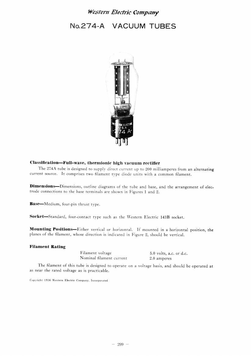
Classifioation-Full-wave, thermionic high vacuum rectifier

The 274A tube is designed to supply direct current up to 200 milliamperes from an alternating
current source. it comprises two filament type diode units with a common filament.

Dimensions-Dimensions, outline diagrams of the tube and base, and the arrangement of elec-
trode connections to the base terminals are shown in Figures 1 and 2.

Base-Medium, {ounpin thrust type.
Socket-Standard, founcontact type such as the \Vestern Electric 1433 socket.

Mounting Positions-Either vertical or horizontal. If mounted in a horizontal position, the
planes at the filament, whose direction is indicated in Figure 2, should be vertical.

Filament Rating

Filament voltage 50 volts, a.c. or d.C.
Nominal filament current 2.0 amperes

The filament of this tube is designed to operate on a voltage basis, and should be operated at
as near the rated voltage as is practicable.

(autumn ism; Western Eli-chic rmupmy. Incurpnrmed

7299,

Page 2

Western Electric Company

No.274-A VACUUM TUBES

Characteristics-l'he current-voltage characteristic of a single diode unit of the 274A tube is
shown in Figure 3. The voltage is measured between the plate and a center tap on the filament
transformer, Directevoltage output characteristics as functions of the direct load current for a
number of values of applied alternating voltage are given in Figures 4 and 5. The characteristics
of Figure 4 are for a choke-input filter such as is shown in circuit A, and those of Figure 5 are for
a condensehinput filter such as is shown in circuit B.

Operating Conditions

R-M-S
Alternating Total
Voltage Bectifled
per Plate Current
Volts Milliamperes
Chokelnput Filter ............... . ..... 550 160
*550 200
*660 160
Condenserelnput Filter .................... 450 140
4150 M150

Maximum operating eopditionsr _
4 MF. maximum filter input capacitance

A less severe condition should be selected in preference to a maximum operating condition
wherever possible. The life of the tube at maximum conditions may be shorter than at less severe
conditions.

Double the above listed values of rectified current may be obtained from two tubes by con-
necting the two plates of each tube together, and using one tube in each side of the circuit.

Eflect 0f Filter-It is evident from the regulation characteristics of Figures 4 and 5 that for a
given output current and voltage, the choke-input filter requires a somewhat higher alternating
Voltage applied to the plates of the tube than the condenser-input filter. With the condenser-
input filter, however, the normal charging and discharging of the condenser each half cycle requires
the tube to supply relatively large peaks of current during each charging period. The peak current
increases in value as the capacitance of the condenser is increased and may be much larger than the
average rectified output current, though its duration in such cases is only a short fraction of a cycle.
Since for good tube performance, the anode current must be considerably less at every part of the
cycle than the total emission current from the filament, the maximum permissible output current
must be limited to such a value that this condition is satisfied. The permissible output current
may be larger, therefore, for a chokeeinput filter, in which the peak anode current is only slightly
larger than the output current. The choke-input filter also gives much better regulation than
the condenser-input circuit. The chokeeinput filter, therefore, should always be selected in preil
erence to the Condensereinput filter wherever possible. \Vith a condenserrinput filter, the capaci-
tance of the input condenser should preferably not exceed 4 microfarads.

7300*