Western electric 262 b brochure

This is the 6 pages manual for western electric 262 b brochure.
Read or download the pdf for free. If you want to contribute, please mail your pdfs to info@audioservicemanuals.com.

Page: 1 / 6
left right
western electric 262 b brochure

Extracted text from western electric 262 b brochure (Ocr-read)


Page 1

BEll. SYSTEM PRACTICES SECTION AB46.262|§
TRANSMISSION ENGINEERING AND DATA ISSUE 1, APRIL 1948
ELECTRON TUBE DATA A.T.&T. CO. STANDARD

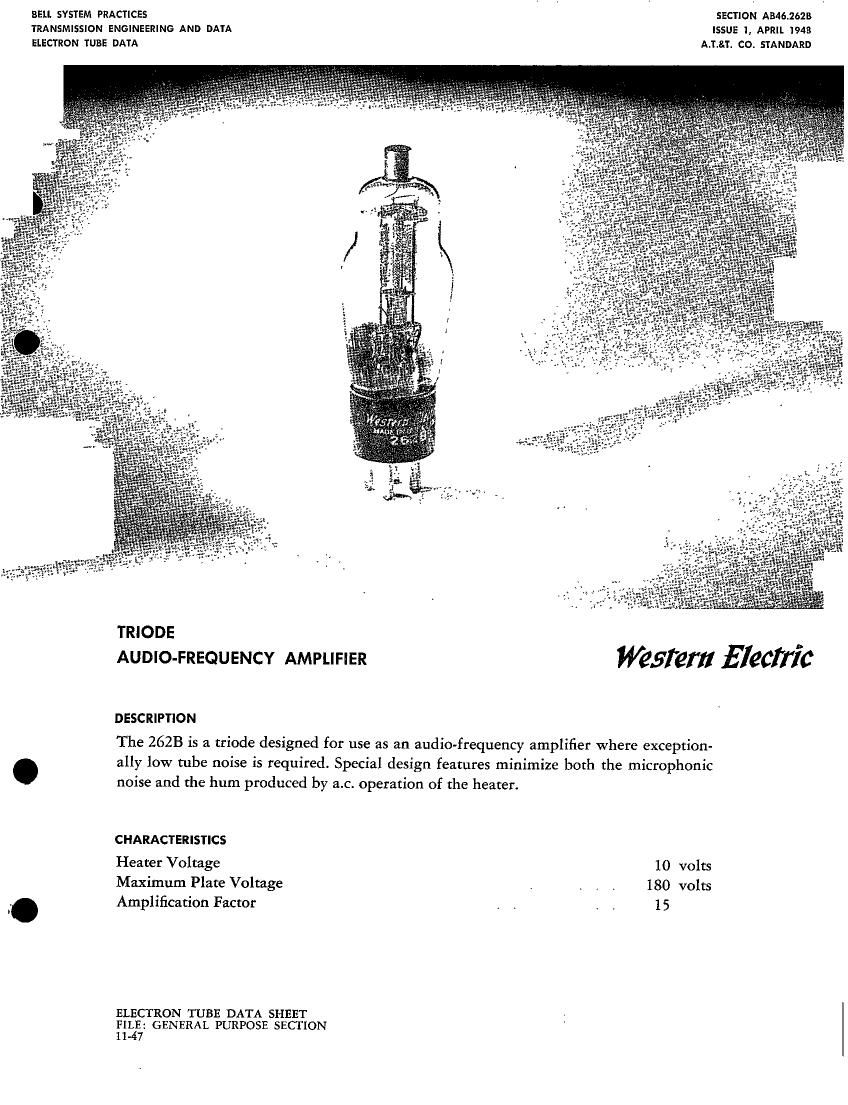
TRIODE
AUDIO-FREQUENCY AMPLIFIER Wafer EleCITIC

DESCRIPTION

The 2628 is a triode designed for use as an audio-frequency amplifier Where exception-
ally low tube noise is required. Special design features minimize both the microphonic
noise and the hum produced by a.c. operation of the heater.

CHARACTERISTICS

Heater Voltage 10 volts
Maximum Plate Voltage i . i . 180 volts
Amplification Factor . . . . 15

ELECTRON TUBE DATA SHEET
F133: GENERAL PURPOSE SECTION
11 7

Page 2

262B - PAGE 2
GENERAL CHARACTERISTICS

ELECTRICAL DATA

Heater Voltage, A-C or D-C
Heater Current

10 volts
320 milliamperes

Direct Interelectrode Capacitances (without external shield)

Grid to Plate
Input
Output

MECHANICAL DATA

Cathode

Bulb

Bae

Mounting Position

1.9 uuf
2.4 uuf
3.8 uuf

Coated Unipotential
ST 12

Small 4-pin

Any

Dimensions and pin connections shown in outline drawing on

Page 3

MAXIMUM RATINGS, Design-Center Values

Plate Voltage

Plate Dissipation

Plate Current
Heater-Cathode Voltage

180 volts
2.0 watts
10.0 milliampetes
30 volts

TYPICAL OPERATING CONDITIONS AND CHARACTERISTICS-CLASS A1 AMPLIFIER

Plate Voltage 120
Grid Voltage -6.0
Peak A-F Grid Voltage 6.0
Plate Current 1.0
Transconductance 560

14.8

Amplification Factor

Plate Resistance 26600
Load Resistance 100000
Maximum Signal Power Output 24
Total Harmonic Distortion 4

HUM

Under typical operating conditions, and with
the cathode of the tube connected to the mid-
point of the heater circuit. the equivalent
hum voltage in the grid circuit will be less
than 12 microvolrs at the supply frequency
and less than 5.0 microvolrs at double the

155 160 180 volts
74.5 *6.0 77.5 volts
4.5 6.0 7.5 volts
3.0 3.0 . 2.8 milliamperes
890 880 840 micromhos
1 5.4 1 5.5 15.3
17300 17700 18300 Ohms
100000 100000 100000 Ohms
18 31 48 milliwatfs
2.5 3 3 percent

supply frequency.

If the insulation leakage and capacitance be-
tween the external grid and heater connec-
tions are kept reasonably low. a resistance of
2 megohms may be used in the grid circuit
without materially affecting the bum level.