Western electric 233 b brochure

This is the 4 pages manual for western electric 233 b brochure.
Read or download the pdf for free. If you want to contribute, please mail your pdfs to info@audioservicemanuals.com.

Page: 1 / 4
left right
western electric 233 b brochure

Extracted text from western electric 233 b brochure (Ocr-read)


Page 1

233B

BELL SYSTEM PRACTICES SECTION AB46.175
Transmission Engineering and Data Issue 1, August 1941
Vacuum Tube Data : A T & T Co a Spedal

Western Electric
233B Vacuum Tube

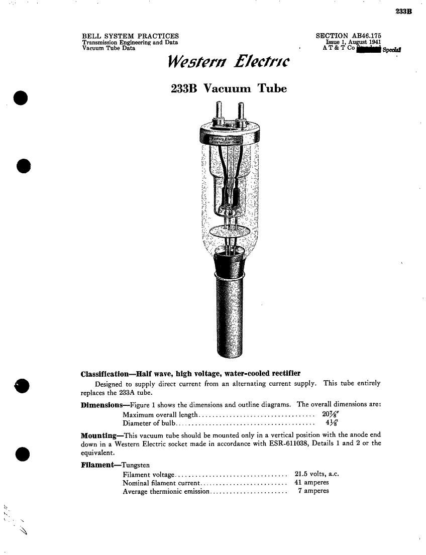
Classification-Half wave, high voltage, water-cooled rectifier

Designed to supply direct current from an alternating current supply. This tube entirely
replaces the 233A tube.

Dimensions-Figure 1 shows the dimensions and outline diagrams. The overall dimensions are:

Maximum overall length .................................. 20%
Diameter of bulb ......................................... 4%

Mounting-This vacuum tube should be mounted only in a vertical position with the anode end
down in a Western Electric socket made in accordance with ESR-611038, Details 1 and 2 or the
equivalent.

Filament-Tungsten
Filament voltage ................................. 21.5 volts, a.c.
Nominal filament current .......................... 41 ampere:

Average thermionic emission ....................... 7 amperes

Page 2

Characteristics and Operating Condition

Maximum peak inverse voltage .................... 50,000 volts
Maximum peak plate current ...................... 5 amperes

The maximum permissible peak plate current (5 amperes) is a limitation on the instantaneous
value that the tube can carry safely in the direction in which it is designed to conduct and should
not be exceeded. The maximum rectified load current is not fixed but will depend upon the wave
form required by the load and filter circuit.

The maximum permissible peak inverse voltage (50,000 volts) is a limitation on the instanta-
neous value that the tube can stand safely in the opposite direction to that in' which it is designed
to Conduct. If it is exceeded, an areback may result which will injure the tube. The maximum
direct potential available is not fixed but will depend upon the type of circuit used.

2333 vacuum tubes ma'y be operated in parallel if some provision is made to insure a proper
division of the load current. Resistors in the heating circuit of each filament may be used for
this purpose.

Operating Precautions
Mechanical-Figure 1 shows the overall dimensions and basing arrangement for the tube.

The tubes should not bersubjected to mechanical shock or excessive vibration. Mechanical
vibration may cause breakage of the tungsten filament. Care should always be used in handling
the tube to avoid scratches on the glass envelope as these may develop into cracks which result
in leaks.

A free circulation of air must be provided to insure adequate cooling of the glass during
operation.

The cooling water should be of sufficient purity to retard the tendency to- form scale on the
anode. Formation of scale would have the effect of insulating the anode from the water and the
inefi'ective cooling of the anode would result in failure of the tube. It is therefore recommended
that distilled water he used in the cooling system.

The temperature of the water and rate of How should be such that there is no tendency for
the water to boil, as indicated by a hissing sound, under maximum dissipation. In general, the
outlet water temperature should not exceed 75° C. and the rate of How should be not less than
1 gallon per minute. The minimum length of water column which can be used to insulate the
plate from the water supply, which is usually grounded, will depend upon the resistivity of the
water used and the leakage current that can be tolerated. This length should not be less than
15 feet. The cooling connections must always be made so that the water flows in at the center
port of the tube socket.

The number of water coils required will depend upon the type of circuit in which the tubes
are used. For example in Circuit B, although there are four tubes used, only two cooling coils are
required since two of the anodes are permanently at ground potential. On the other hand the
corresponding filament circuits reach peak alternating potential above ground and must be in-
sulated accordingly.

Provision should be made in the circuit to safeguard against filament and plate voltages being
applied until cooling water is circulating at the proper rate and temperatures, and for immediate
cut-ofir of filament and plate voltages if the circulating rate falls below the allowed minimum or the
temperature exceeds the allowable maximum. A momentary interruption of the water circulation
during operation of the tube may cause inunediate failure.

Electrical-Overload protection should always be provided for the plate circuit. Although
the tube is sufiiciently rugged to withstand momentary overloads, a prolonged overload caused by
inefficient adjustment of the circuit, may damage the tube.

[2]