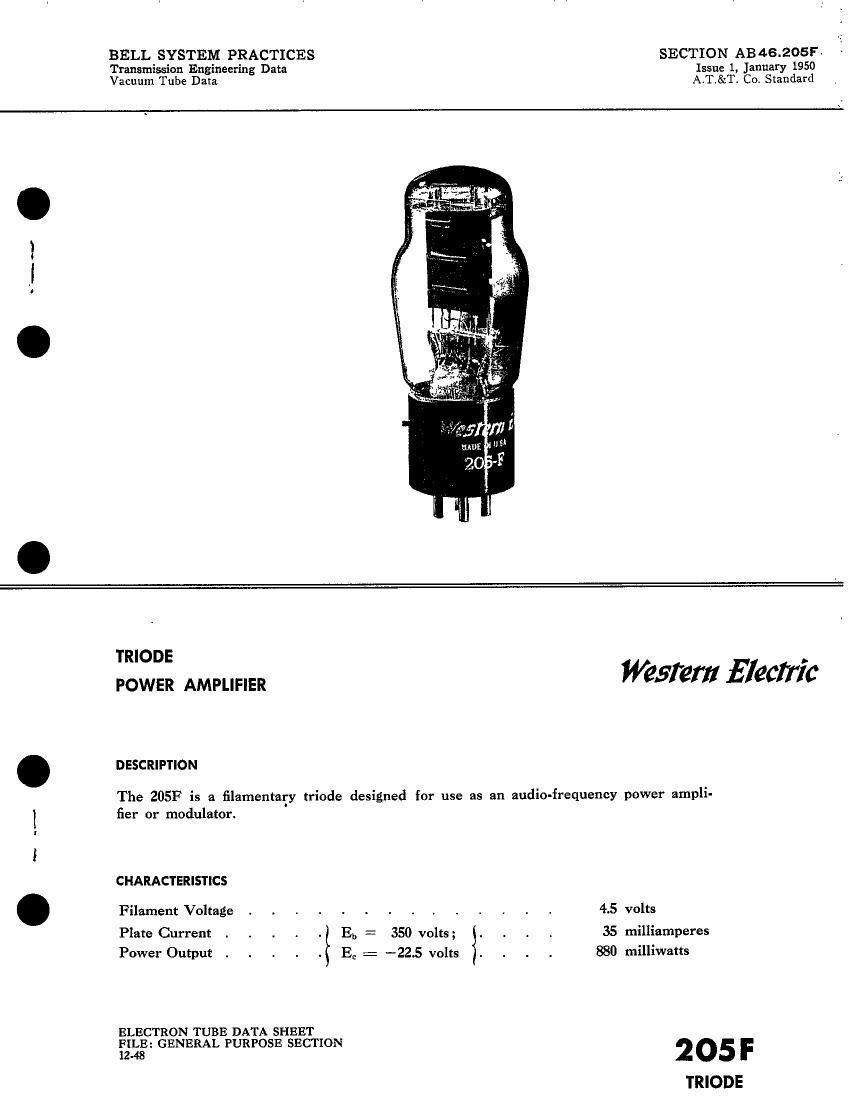
Western electric 205 f brochure

This is the 6 pages manual for western electric 205 f brochure.
Read or download the pdf for free. If you want to contribute, please mail your pdfs to info@audioservicemanuals.com.

Page: 1 / 6
left right
western electric 205 f brochure

Extracted text from western electric 205 f brochure (Ocr-read)


Page 2

205F - PAGE 2

GENERAL CHARACTERISTICS

ELECTRICAL DATA

Filament Voltage, A-C or D-C ,
Filament Current
Direct Interelectrode Capacitances
Grid to Plate .
Input
Output

MECHANICAL DATA

Cathode
Base

Mounting Position

45 volts
1.6 amperes

5.9 not
4.1 nut
22 uuf

. . . . . Coated Filament
Medium 4-pin, bayonet type with bayonet
pin offset

Preferably vertical; if horizontal, pins #1 and
#2 must lie in same vertical plane

Dimensions and pin connections shown in outline drawing on Page 5

MAXIMUM RATINGS, Design-Center Values
Plate Voltage .

Plate Current .

Plate Dissipation .

TYPICAL OPERATING CONDITIONS AND CHARACTERISTICS

Filament Voltage, A-C

Plate Voltage . .

Grid \v'oltageE . . . .

Peak A-F Signal Voltage .

Zero Signal Plate Current
Maximum Signal Plate Current ,
Transconductance

Plate Resistance

Load Resistance

Amplification Factor . . .
Maximum Signal Power Output 1
Total Harmonic Distortion

360 volts
50 milliamperes
12.5 watts
4.5 4.5 4.5 4.5 volts
250 300 350 350 volts
-22 -18 -22.5 -225 volts
22 18 22.5 2.5 volts
11.5 30 35 35 milliamperes
12 30.5 36 36 milliamperes

1350 1880 1950 1950 micromhos
5300 3800 3700 3700 ohms
12000 8000 4000 8000 ohms

7.2 7.2 72 7.2
550 450 880 760 milliwatts
4.6 1.6 2.8 1.4 per cent

If the filament is operated on DC. the characteristics will be approximately the same
if the grid voltage. measured from the negative filament, is decreased by 2.3 volts.