Western electric 205 e brochure

This is the 8 pages manual for western electric 205 e brochure.
Read or download the pdf for free. If you want to contribute, please mail your pdfs to info@audioservicemanuals.com.

Page: 1 / 8
left right
western electric 205 e brochure

Extracted text from western electric 205 e brochure (Ocr-read)


Page 1

BELL SYSTEM PRACTICES SECTION AB46.091
Transmission Engineering and Data Issue 1, September 1936
Vacuum Tube Data A T & T Co Standard

Weary/'17 Electric
205E Vacuum Tube

Classification-Moderate power, filamentary triode

The 205E tube is similar to the 205D tube except that special precautions have been taken in
the 205E tube to minimize sputter noise in the tube and contact noise between the contact pins
and the socket.

Applications

Audio-frequency amplifier or modulator where power outputs of approximately 1 watt or less
are required.

Radio-frequency power amplifier.

Oscillator.

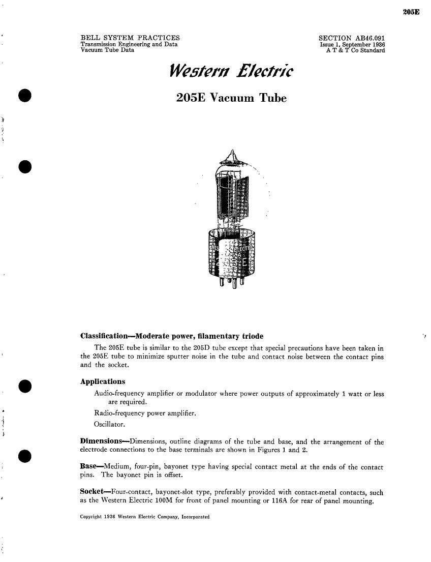
Dimensions-Dimensions, outline diagrams of the tube and base, and the arrangement of the
electrode connections to the base terminals are shown in Figures 1 and 2.

Base-Medium, four-pin, bayonet type having special contact metal at the ends of the contact
pins. The bayonet pin is offset.

Socket-Four-contact, bayonet-slot type, preferably provided with contact-metal contacts, such
as the Western Electric 100M for front of panel mounting or 116A for rear of panel mounting.

Copyright 1936 Western Electric Company, Incorporated

205E

Page 2

Mounting Positions-Either vertical or horizontal. If mounted in a horizontal position, the
plane of the filament. which is indicated in Figure 2. should be vertical

Average Direct Interelectrode Capacitances

A B C
Grid to plate, [1pr ......... 4.8 4.3 4.3
Grid to filament, pill. 5.2 6.4 6.9
Plate to filament, poi. . . . . , ................ 3.3 5.2 5.5

Column AiBased tube Without socket.

Column Be-Tube alone when measured in 10031 socket mounted on metal plate; socket and
mounting plate connected to filament.

Column C-Tube alone when measured in 116A socket mounted in metal plate; socket and
mounting plate connected to filament.

Filament-Oxide-coated
Filament voltage. ......... . ................ 4.5 volts, a.c. or d.c.

Nominal filament current ...... . ............. 1.6 amperes

The filament of this tube is designed to operate on a voltage basis and should be operated at
as near the rated voltage as is practicable. When alternating-current filament supply is used, the
grid and plate returns should be connected to a center tap on the secondary of the filament trans-
former.

Characteristics-Plate current charcreristics of a typical 205E tube are shown in Figure 3 as
functions of grid voltage for several values of plate voltage. Corresponding amplification factor,
plate resistance, and transconductance characteristics are given in Figures 4, 5, and 6, respectively.
Plate current characteristics as functions of plate voltage for several values of grid voltage are
shown in Figure 7. These characteristics are for direct-current filament supply with the grid and
plate voltages measured from the negative end of the filament. When alternating-current filament
supply is used, the same characteristics are applicable if 2.6 is added to the numerical value of each

grid bias.

)Iicrophonit Noise-With a plate voltage of 350 volts, a grid bias of -22.5 volts, and a load
resistance of 100,000 ohms, the mean microphonic noise output level of 205E tube measured
in a laboratory reference test set is 25 decibels below 1 volt. The range of levels of individual tubes
extends from 16 to 33 decibels below 1 volt. Since microphonic noise depends on the type and
intensity of the mechanical disturbance which produces it, the values given here are useful chiefly
for comparison with the levels of other tubes which have been tested in the same way.

Sputtel Noise-A particularly disagreeable type of noise, characterized by an unmusical crackling
or sputtering sound, occurs in many vacuum tubes, sometimes as a result of slight mechanical
agitation. The sputter noise spectrum covers a wide band and may be of appreciable intensity even
at radio frequencies. Such noise is usually due either to discontinuously variable insulation leaks

l2]